Online Banking is one of the few BSIT capstone topics where panels actually scrutinize the sequence diagram. For an Inventory or Library project, the sequence diagram is filler.
For a banking project, it’s the diagram that proves you thought through the security flow, the transaction sequence, and the error handling.
A sequence diagram for “view balance” is trivial, three messages and done. A sequence diagram for “money transfer with two-factor authentication” is the kind that wins defenses.
This guide walks through the complete money transfer sequence diagram with lifelines, activation boxes, synchronous and asynchronous messages, alt fragments for error cases, and the OTP-verification flow panels expect to see for any financial capstone.
For other workflows (login, bill payment, balance inquiry), you can adapt this structure by swapping the participants and messages.
What a sequence diagram actually shows
A Sequence Diagram shows the INTERACTION between participants over TIME. Three things it captures:
- Who’s involved: actors and objects (participants)
- What they say to each other: messages with method calls and parameters
- When things happen: vertical axis goes top-to-bottom in time order
Sequence diagrams are different from class diagrams (which show static structure) and from activity diagrams (which show flow without who-does-what). Use sequence diagrams when the order of who-talks-to-who matters, banking transactions are the textbook example.
Sequence diagrams live in Chapter 3, Section 3.6 (System Design), typically after the static diagrams (Use Case, Class, ER) and before Activity Diagrams. For the general sequence diagram guide covering all UML conventions, see our Sequence Diagram guide.
The 6 elements of every sequence diagram
Six building blocks.
1. Actor or Object (rectangle at top)
A participant in the interaction. Actors are people (Customer); objects are system components (BankingService, Database).
Drawn as a rectangle at the top of the diagram with the name inside. Actors may also use the stick-figure notation from use case diagrams.
2. Lifeline (vertical dashed line)
A dashed vertical line going down from each participant. Represents the lifetime of that participant during the interaction.
If a participant is “destroyed” mid-sequence, their lifeline ends with an X.
3. Activation Box (narrow vertical rectangle)
A thin vertical rectangle on a lifeline showing when that object is actively doing work (executing a method).
Activation boxes appear when an object receives a message and disappear when the work is done. They’re optional in some notations but recommended for clarity.
4. Message (horizontal arrow)
A horizontal arrow from one lifeline to another, labeled with the method name and parameters being called.
The arrow direction shows who’s calling whom. Vertical position shows when in time it happens (earlier messages higher on the page).
5. Return Message (dashed horizontal arrow)
A dashed arrow returning a value. Optional but recommended when the return value is meaningful.
Example: success or account_balance: 5000.00
6. Self-message (curved arrow)
A message from an object to itself. Drawn as a small arc that goes out and comes back to the same lifeline.
Used when an object calls one of its own methods internally.
Message types: synchronous vs asynchronous
The arrow style tells you the message type.
Synchronous message (solid arrow with filled triangle)
──────────► with filled triangle head
- The caller waits for the response before continuing
- Standard method call in most code
- Most common message type
- Example:
withdraw(500.00), caller waits for success/failure return
Asynchronous message (solid arrow with open triangle)
──────────▷ with open/skeletal triangle head
- The caller doesn’t wait, fire and forget
- Used for events, notifications, queue messages
- Example:
sendSMSNotification(message), caller continues immediately
Return message (dashed arrow)
- - - - - - -►
- Response from a synchronous call
- Drawn as dashed line, often with the return value labeled
- Can be omitted if the return is implicit or obvious
Create message (with <<create>> label)
When a new object is created during the sequence:
──<<create>>──► pointing to a NEW lifeline starting at that moment
Destroy message (X at end of lifeline)
When an object is destroyed:
────X at the bottom of the destroyed lifeline
Rarely needed in BSIT capstones unless you’re modeling explicit memory management.
Combined fragments: the section most students skip
UML 2.0 added “combined fragments”, boxes drawn around parts of the sequence to show alternative or repeated behavior. Without them, you can only draw the “happy path.” Add them to show real-world conditions.
alt (alternatives): if/else branches
A rectangle with alt in the top-left, divided horizontally by a dashed line. Each section is a different branch.
Use for: “if balance >= amount THEN proceed ELSE return error”
opt (optional): single conditional branch
A rectangle with opt in the top-left. The content executes only if a condition is true; no else branch.
Use for: “if customer has SMS notifications enabled, send confirmation SMS”
loop: repeated behavior
A rectangle with loop in the top-left and the loop condition in brackets.
Use for: “for each item in the order, validate inventory”
par (parallel): concurrent execution
A rectangle with par in the top-left. Sections execute in parallel.
Use for: “simultaneously update account balance AND send notification”
ref (reference): reference to another sequence diagram
A rectangle with ref in the top-left and the name of the referenced sequence.
Use for: “see Sequence Diagram for Authentication”, avoids duplicating common flows.
For a typical BSIT capstone, you’ll use alt (most common) and opt (occasionally). Skip par and loop unless they genuinely apply to your workflow.
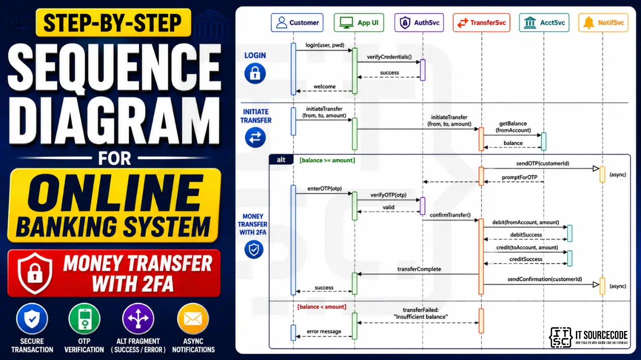
Online Banking System: the money transfer workflow
For this guide, we model the highest-value workflow in an online banking system: money transfer with two-factor authentication. This single workflow demonstrates more sequence-diagram elements than any other banking operation.
Participants (6)
| Participant | Role |
|---|---|
| Customer | Actor, initiates the transfer |
| App UI | The banking app’s user interface layer |
| AuthenticationService | Verifies credentials and OTP |
| AccountService | Manages account balances and transactions |
| TransferService | Coordinates the transfer logic |
| NotificationService | Sends SMS/email confirmations |
Workflow overview
- Customer logs in (UI → Auth)
- Customer initiates transfer (UI → TransferService)
- System validates balance (TransferService → AccountService)
- System sends OTP for 2FA (TransferService → NotificationService)
- Customer enters OTP (UI)
- System verifies OTP (UI → AuthenticationService)
- System executes transfer (TransferService → AccountService for both accounts)
- System confirms transfer (UI shows success)
- System sends confirmation notification (TransferService → NotificationService)
The whole workflow takes 9 message-level interactions plus an alt fragment for the insufficient-balance case.
The complete sequence diagram
Here’s the representation of the full money transfer sequence:
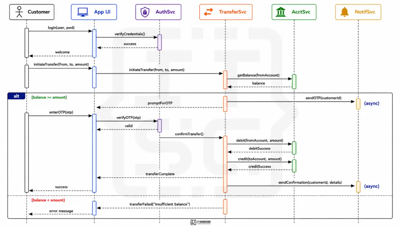
Key things to notice:
- Time flows top-to-bottom
- Solid arrows are synchronous (caller waits)
(async)notes indicate asynchronous messages- Dashed arrows are returns
- The
altfragment wraps the branch on balance check - Both branches (sufficient vs insufficient balance) are shown
Step-by-step walkthrough
Step 1-3: Login flow. Customer sends credentials to the App UI. UI calls AuthenticationService.verifyCredentials(). On success, UI sends welcome back to Customer.
Step 4-5: Initiate transfer. Customer enters transfer details (from account, to account, amount) in the UI. UI forwards to TransferService, which calls AccountService.getBalance(fromAccount) to check funds.
Step 6 (alt branch): Balance check. This is the alt fragment. If balance >= amount, proceed to OTP. If balance < amount, return error to Customer.
Step 7: OTP send (sufficient balance branch). TransferService asks NotificationService to send OTP. This is an asynchronous message, TransferService doesn’t wait for the SMS to arrive; it returns immediately and waits for the user to enter the OTP back.
Step 8: OTP verification. Customer enters the OTP they received via SMS. UI calls AuthenticationService.verifyOTP(). On success, UI calls TransferService.confirmTransfer().
Step 9: Execute transfer. TransferService calls AccountService twice: debit fromAccount and credit toAccount. Both are synchronous, the transfer doesn’t complete until both succeed.
Step 10: Confirm and notify. UI shows success to Customer. TransferService asynchronously sends confirmation to NotificationService (which sends SMS/email).
Insufficient balance branch: If the balance check fails in step 6, TransferService immediately returns “Insufficient balance” to UI, which displays error to Customer. No OTP, no transfer executed.
From sequence diagram to Java code
Sample Java method showing how the diagram maps to actual TransferService implementation:
public class TransferService {

    private AccountService accountService;
    private AuthenticationService authService;
    private NotificationService notificationService;

    public TransferResult initiateTransfer(int customerId, int fromId, int toId, double amount) {
        // Step 6: Balance check (the alt fragment)
        Account fromAccount = accountService.getAccount(fromId);
        if (fromAccount.getBalance() < amount) {
            return TransferResult.fail("Insufficient balance");
        }

        // Step 7: Send OTP (asynchronous)
        notificationService.sendOTPAsync(customerId);

        // Return state: waiting for OTP
        return TransferResult.pending("Enter OTP to confirm transfer");
    }

    public TransferResult confirmTransfer(int customerId, int fromId, int toId, double amount, String otp) {
        // Step 8: OTP verification
        if (!authService.verifyOTP(customerId, otp)) {
            return TransferResult.fail("Invalid or expired OTP");
        }

        // Step 9: Execute transfer (both must succeed)
        accountService.debit(fromId, amount);
        accountService.credit(toId, amount);

        // Step 10: Send confirmation (asynchronous)
        notificationService.sendConfirmationAsync(customerId, amount);

        return TransferResult.success("Transfer complete");
    }
}
The diagram’s alt fragment becomes an if/else in code. The asynchronous messages become *Async() method calls. Synchronous messages become regular method calls where the caller waits.
Common sequence diagram mistakes that get sent back
Eight patterns we see in BSIT defenses:
- Reading bottom-to-top. Sequence diagrams go TOP-to-bottom. Earliest events at the top.
- Mixing up synchronous and asynchronous arrow heads. Solid filled triangle = sync. Open triangle = async. Get this wrong and the panel will assume your code blocks where it shouldn’t (or vice versa).
- Forgetting return messages. When the caller needs the return value, show the dashed return arrow. Otherwise the panel can’t tell where the data came from.
- No alt fragment for error cases. Every workflow has failure paths. If your diagram only shows the happy path, panels assume you didn’t think about errors.
- Activation boxes missing. Without the narrow vertical rectangle on lifelines, the reader can’t tell when an object is actively working.
- Too many participants. Above 8 participants, the diagram becomes unreadable. Split into multiple diagrams or simplify.
- Showing UI buttons as separate participants. “LoginButton” and “TransferButton” should NOT be separate participants. They’re part of the UI participant. One UI = one lifeline.
- Putting too much detail. One sequence diagram = ONE workflow. Don’t try to show login AND transfer AND balance check in the same diagram.
How to draw your sequence diagram: tool recommendations
PlantUML (free, recommended for sequence diagrams)
Sequence diagrams are PlantUML’s strongest output. You write text, PlantUML renders. Example:
@startuml
actor Customer
participant "App UI" as UI
participant AuthSvc
participant AcctSvc

Customer -> UI : login(user, pwd)
UI -> AuthSvc : verifyCredentials()
AuthSvc --> UI : success
UI --> Customer : welcome

Customer -> UI : initiateTransfer(from, to, amount)
UI -> AcctSvc : getBalance(fromAccount)
AcctSvc --> UI : balance

alt balance >= amount
    UI -> AcctSvc : debit(from, amount)
    UI -> AcctSvc : credit(to, amount)
    UI --> Customer : success
else balance < amount
    UI --> Customer : "Insufficient balance"
end
@enduml
This produces a perfectly formatted sequence diagram automatically. Best for version control because the source is text.
draw.io (free)
- Has UML sequence diagram template
- Visual drag-and-drop
- Good if you prefer GUI over text
WebSequenceDiagrams.com (free, browser-based)
- Text-input, fast preview
- Export to PNG
- Similar syntax to PlantUML
Lucidchart
- Free tier
- Real-time collaboration
What to avoid: PowerPoint, Word. Sequence diagrams have too many specific notations to draw manually.
How to put your sequence diagram in Chapter 3
Same placement as other UML diagrams: Chapter 3, Section 3.6, with figure number, caption, and explanation paragraph.
Caption format:
Figure 3.X. Sequence Diagram for [Workflow Name] of the [Your System Name].
Important: One diagram = one workflow. Most BSIT capstones include sequence diagrams for the 2 to 3 most complex workflows (login, transaction, payment) and skip trivial ones (view balance, list items).
The explanation paragraph should:
- Name the workflow this diagram represents
- List the participants
- Highlight any alt/opt fragments and what they handle
- Note any asynchronous messages and why
For the full Chapter 3 methodology, see our Chapter 3 Methodology guide.
How to customize for your specific banking system
Different banking variants have different signature workflows. Pick the highest-complexity workflow for your sequence diagram.
- Online banking app (the default): money transfer with 2FA (this guide)
- ATM system: cash withdrawal with PIN verification, card-block on 3 wrong attempts
- Mobile wallet (GCash, Maya, PayMaya): link bank account, peer-to-peer transfer
- Microfinance loan system: loan application, multi-level approval workflow
- Cooperative banking: member deposit, share capital purchase, dividend distribution
- Cryptocurrency wallet: send transaction with gas fee estimation
- Remittance system: sender deposits, conversion, receiver picks up
- Bills payment system: bill lookup, payment authorization, receipt issuance
For each variant, identify the workflow with:
- Most participants (typically 4-6)
- At least one error case (use alt fragment)
- At least one asynchronous message (notification, log)
That’s your strongest sequence diagram candidate.
Free download: sequence diagram template
Frequently Asked Questions
What is a sequence diagram and why is it important for capstone projects?
What is the difference between sequence diagram and activity diagram?
How many participants should be in a sequence diagram?
What is an alt fragment in a sequence diagram?
Where does the sequence diagram go in capstone documentation?
Official documentation
Working source code for this system
Download the actual implementation of this system in your preferred language. Each project includes source code, database, and setup instructions for BSIT capstone use.
- PHP: Online Blood Bank Management System in PHP with Source Code
- VB.NET: Test Bank System of Kabankalan Catholic College
- Java: Bank Management System Project In Java NetBeans Source Code
- Python: Bank Management System Project in Django with Source Code
- Django: Bank Management System Project in Django with Source Code
- Laravel: Online Banking Management System Project in Laravel with Source Code
Frequently Asked Questions
What is a sequence diagram and why is it important for capstone projects?
A Sequence Diagram is a UML diagram that shows the interaction between participants (actors and objects) over time, focusing on the order of messages exchanged during a specific workflow or scenario. For a BSIT capstone, sequence diagrams are required in Chapter 3 Section 3.6 for the 2 to 3 most complex workflows in your system. They are especially important for capstones involving transactions, authentication, or multi-step processes (banking, e-commerce, hospital admissions). Panels use sequence diagrams to verify that you have thought through the order of operations, error handling, and asynchronous communication in your system.
What is the difference between sequence diagram and activity diagram?
A sequence diagram focuses on WHO interacts with WHOM in what order. The participants are visible as columns and time flows top-to-bottom. An activity diagram focuses on the FLOW OF CONTROL: actions, decisions, and loops, without emphasizing who performs each step. Use a sequence diagram when the order of who-talks-to-who matters (banking transactions, authentication flows). Use an activity diagram when the flow has many decision branches or loops but the participants are less important (order processing, report generation). Most BSIT capstones include 1 to 2 sequence diagrams AND 1 to 2 activity diagrams covering different aspects of the system.
How many participants should be in a sequence diagram?
A typical BSIT sequence diagram has 3 to 7 participants. Below 3 participants, the diagram is too simple to justify drawing. Write the workflow as a paragraph instead. Above 8 participants, the diagram becomes unreadable and should be split into multiple sequence diagrams or summarized at a higher level. For online banking transactions, 5 to 6 participants is typical: Customer, UI, Authentication Service, Account Service, Transfer Service, and Notification Service. If your sequence diagram has more than 8 participants, your workflow probably needs decomposition or a different diagram type.
What is an alt fragment in a sequence diagram?
An alt fragment in a sequence diagram represents alternative paths in the workflow, equivalent to if/else branches in code. It is drawn as a rectangle around the relevant messages with alt in the top-left corner. The rectangle is divided horizontally by a dashed line, with each section being a different branch typically labeled with the condition in square brackets. Use alt fragments to show error handling and decision points without drawing separate diagrams for each scenario. Other combined fragments include opt (single optional branch), loop (repeated behavior), and par (parallel execution).
Where does the sequence diagram go in capstone documentation?
The sequence diagram goes in Chapter 3 Section 3.6 (System Design) of your capstone documentation, typically after the use case diagram and class diagram. It is numbered as Figure 3.X with a caption that names the specific workflow it represents (for example, Figure 3.5. Sequence Diagram for Money Transfer Workflow). Most BSIT capstones include 2 to 3 sequence diagrams covering the most complex workflows in the system, not one diagram per workflow. The explanation paragraph in the body text should name the participants, the workflow, and highlight any alt fragments or asynchronous messages.
Pick your workflow. Sketch the participants. Add the messages.
Sequence diagrams start with the workflow. Pick the highest-value, most complex flow in your system, the one with multiple participants, error cases, and notifications. That’s your strongest sequence diagram candidate.
Then list the participants. For each participant, decide if they’re calling or being called. Draw the lifelines. Add the messages from top (earliest) to bottom (latest). Wrap any branching in an alt fragment.
By the time you have 6 participants and 12 messages with one alt fragment, you have a defensible sequence diagram.
For the full Chapter 3 methodology, see our Chapter 3 Methodology guide. For the broader documentation structure, see our Capstone Chapter 1-5 Template. And for sibling UML deep-dives, see our Class Diagram for Library Management System, ER Diagram for Hospital Management System, and DFD for Inventory Management System.
For other UML diagram types, see our UML guides hub. If you haven’t picked your capstone topic yet, browse 150 Best Capstone Project Ideas for IT Students 2026. For working banking source code to study, search our free projects library.
Now open PlantUML or draw.io. Pick one workflow. Add 5 participants. Connect them top to bottom.
One sequence diagram in 20 minutes. Chapter 3 stronger by a section.

Caren Bautista
Technical Writer at PIES IT Solution
Responsible for crafting clear, well-structured, and beginner-friendly content across the platform. Handles the writing, proofreading, and editorial review of tutorials, guides, and documentation to ensure every article is accurate, readable, and easy to follow.
Expertise: Technical Writing · Content Creation · Documentation · Editorial Writing · JavaScript · TypeScript · Python · Python Errors · HTTP Errors · MS Excel · View all posts by Caren Bautista →