Hospital Management System is a top-5 BSIT capstone topic in 2026, and the ER diagram is where your database design becomes defensible. Without a strong ER diagram in Chapter 3, your panel can’t tell whether you actually designed your database or just made tables as you went along.
Most students draw the entities right but mess up three things. They forget cardinality labels. They draw composite attributes as separate entities. And they skip the SQL schema entirely, leaving the panel to guess how the diagram maps to actual code.
This guide walks through the complete ER diagram for a Hospital Management System with 8 entities, all the relationships with proper cardinality, both Chen and Crow’s Foot notation, and the actual SQL CREATE TABLE statements you can paste into MySQL or PostgreSQL. By the end, you’ll have the database design your Chapter 3 needs.

What an ER diagram actually shows
An Entity Relationship Diagram shows the structure of your database from a logical perspective. Three things it captures:
- What you store: entities (things) and attributes (what you know about them)
- How things connect: relationships between entities
- How many connect to how many: cardinality
ER diagrams live in Chapter 3, Section 3.6 (System Design), alongside your DFD and Use Case diagrams. They’re the bridge between conceptual design and the actual database your code will query.
For the general ER diagram guide covering all conventions, see our ER Diagram guide. This post applies those conventions to a hospital management worked example.
The 3 main elements of every ER diagram
Three building blocks. Master these and you can draw ER diagrams for any system.
1. Entity (rectangle)
A thing your database stores data about. Almost always a noun. Examples for hospital systems:
- Patient
- Doctor
- Nurse
- Appointment
- Medical Record
- Prescription
- Department
- Bill
Each entity in your diagram becomes a TABLE in your database. The entity name is singular by convention (Patient, not Patients), the table itself will hold many rows.
2. Attribute (oval in Chen notation)
What you know about an entity. The columns of your table.
Examples for Patient:
- patient_id (key)
- name
- date_of_birth
- gender
- address
- phone
Attributes attach to entities with a line. In Chen notation, attributes are ovals. In Crow’s Foot notation, attributes are listed inside the entity rectangle.
3. Relationship (diamond in Chen notation)
How entities connect to each other. Almost always a verb.
Examples:
- Patient SCHEDULES Appointment
- Doctor CONDUCTS Appointment
- Doctor PRESCRIBES Prescription
- Doctor BELONGS_TO Department
Each relationship in your ER diagram becomes either a foreign key or a junction table in your SQL schema, depending on cardinality.
Free tool
Generate this ER Diagram in 3 minutes
You have the structure. Now build it with your own entities. The Hospital Management template comes pre-filled, so you rename what does not match your project and export straight into your Chapter 3.
Open the Hospital Management template →3 free diagrams every week. No credit card needed.
5 attribute types every BSIT student should know
Not all attributes are simple. Five types, with how to draw and use each.
1. Simple attribute. Single value, cannot be broken down further. Example: gender, age, dosage.
2. Composite attribute. Made of multiple parts that can stand alone. Example: address = (street + city + province + zip). Drawn as an oval with sub-ovals attached.
3. Derived attribute. Computed from other attributes. Example: age (derived from date_of_birth). Drawn as a dashed oval. In SQL, derived attributes are usually computed in queries, not stored.
4. Multivalued attribute. Multiple values for one instance. Example: a Patient with multiple phone_numbers. Drawn as a double oval. In SQL, multivalued attributes become a separate table.
5. Key attribute. Uniquely identifies an instance. Example: patient_id. Drawn with the name underlined. Maps to PRIMARY KEY in SQL.
Cardinality: the most-misunderstood concept
Cardinality means: how many of one entity can relate to how many of another. Get this wrong and your panel will catch it in 10 seconds.
Three cardinality types:
1:1 (One-to-One)
One entity instance relates to exactly one instance of another.
Example: Patient has one Patient Profile.
In SQL: a foreign key in either table, often with a UNIQUE constraint.
1:1 is rare. If you have it, ask yourself whether the two entities should really be one.
1:N (One-to-Many): most common
One entity instance relates to many of another, but each on the “many” side relates to only one on the “one” side.
Example: Doctor PRESCRIBES many Prescriptions. Each Prescription is written by exactly one Doctor.
In SQL: foreign key on the “many” side. The Prescription table has a doctor_id column referencing Doctor.
M:N (Many-to-Many)
Many instances of one entity relate to many of another.
Example: Patient is TREATED_BY many Doctors. Doctor TREATS many Patients.
In SQL: requires a junction table (also called a join table or associative entity). For Patient-Doctor M:N, you’d create a patient_doctor table with patient_id and doctor_id columns.
Participation: total vs partial
A second dimension beyond cardinality.
Total participation (mandatory): Every instance must participate in the relationship. Drawn as a double line.
- Example: Every Appointment must be scheduled by a Patient. (No Appointment without a Patient.)
Partial participation (optional): Instances may or may not participate. Drawn as a single line.
- Example: A Patient may or may not have an Appointment scheduled. (Some patients haven’t booked.)
In SQL, total participation typically maps to NOT NULL on foreign keys. Partial participation allows NULL.
Chen notation vs Crow’s Foot notation
Two notation systems. Pick one and stay consistent.
| Element | Chen | Crow’s Foot |
|---|---|---|
| Entity | Rectangle | Rectangle |
| Attribute | Oval connected by line | Listed inside the entity rectangle |
| Relationship | Diamond between entities | Line directly between entities |
| Cardinality | “1”, “N”, “M” labels near entities | “Crow’s feet” or “single bar” symbols at line ends |
| Participation | Single or double line | Solid circle (mandatory) or empty circle (optional) |
Filipino BSIT capstones traditionally use Chen notation because it’s introduced earlier in the database curriculum. Modern database design tools (MySQL Workbench, dbdiagram.io, draw.io) lean toward Crow’s Foot.
For this guide, we’ll use Chen notation in the diagrams but show Crow’s Foot equivalents in the notation reference. Both are valid for BSIT capstones.
Hospital Management System: the example context
For this guide, we model a typical hospital management system. Adapt to your specific hospital type (general, pediatric, mental health, dental, veterinary).
Entities (8 total)
| Entity | Purpose |
|---|---|
| Patient | Stores patient personal and medical information |
| Doctor | Stores doctor credentials and contact info |
| Nurse | Stores nurse credentials and shift info |
| Department | Hospital departments (Cardiology, Pediatrics, etc.) |
| Appointment | Patient-Doctor scheduled meetings |
| Medical Record | Doctor’s written record of patient visits |
| Prescription | Medications prescribed by doctors |
| Bill | Patient billing and payment tracking |
Key attributes per entity
- Patient: patient_id (PK), name, date_of_birth, gender, address, phone
- Doctor: doctor_id (PK), name, specialization, license_no, phone, dept_id (FK)
- Nurse: nurse_id (PK), name, shift, phone, dept_id (FK)
- Department: dept_id (PK), dept_name, location
- Appointment: appt_id (PK), date, time, status, reason, patient_id (FK), doctor_id (FK)
- Medical Record: record_id (PK), diagnosis, treatment_notes, date, patient_id (FK), doctor_id (FK)
- Prescription: prescription_id (PK), medication, dosage, frequency, date, doctor_id (FK), patient_id (FK)
- Bill: bill_id (PK), total_amount, payment_status, billing_date, patient_id (FK)
The complete ER diagram
Here’s the representation of the full diagram with all entities, key attributes, and relationships:
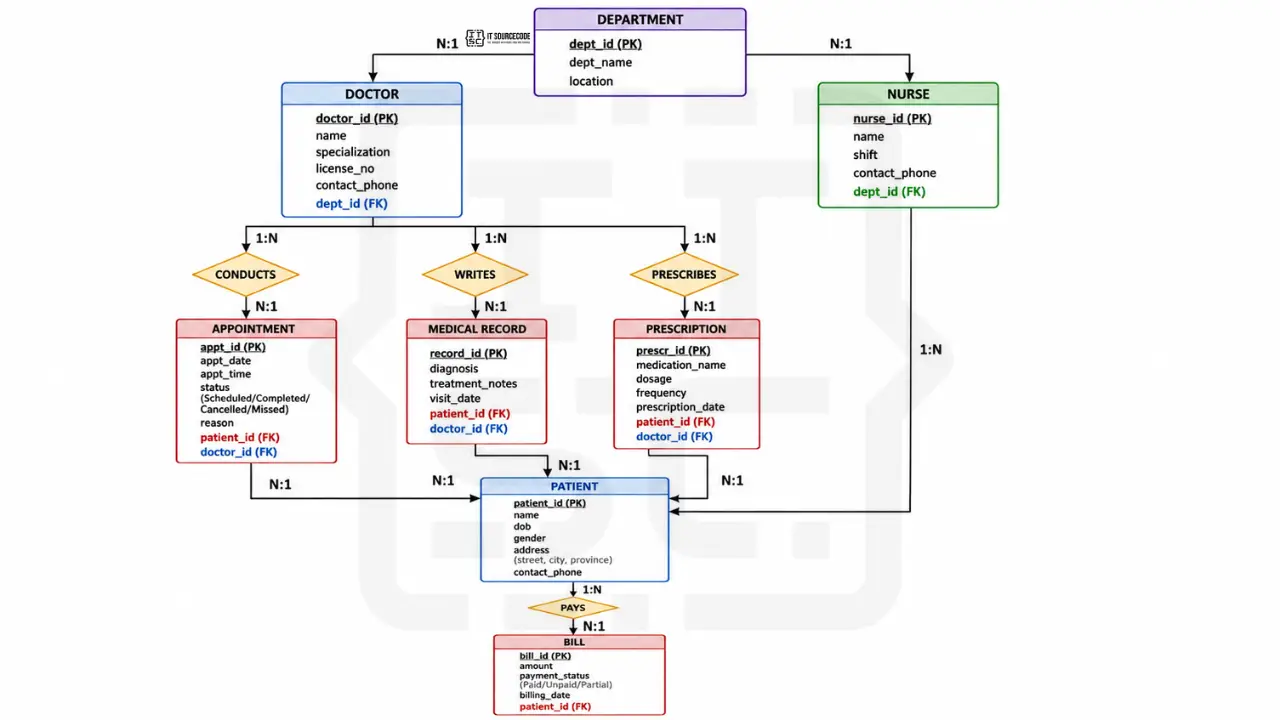
Cardinality summary:
- Patient (1) ─── (N) Appointment
- Doctor (1) ─── (N) Appointment
- Doctor (1) ─── (N) Medical Record
- Patient (1) ─── (N) Medical Record
- Doctor (1) ─── (N) Prescription
- Patient (1) ─── (N) Prescription
- Patient (1) ─── (N) Bill
- Doctor (N) ─── (1) Department
- Nurse (N) ─── (1) Department
All relationships in this design are 1:N. No 1:1 or M:N. This is a deliberate simplification, many real hospital systems have an M:N “Patient TREATED_BY Doctor” relationship, but for a BSIT capstone, the 1:N design via Appointment is cleaner and easier to defend.
Every entity explained
Patient: the central entity of any hospital system. Stores all personal information including name, date of birth (used to compute age as a derived attribute), gender, address (composite attribute: street + city + province), and contact phone. Patient_id is the primary key.
Doctor: stores doctor credentials including name, specialization (Cardiology, Pediatrics, etc.), license number for verification, and contact phone. Each Doctor belongs to one Department via the dept_id foreign key.
Nurse: similar to Doctor but tracks shift schedule instead of specialization. Each Nurse works in one Department.
Department: hospital departments like Cardiology, Pediatrics, Surgery, Emergency. Has a name and physical location within the hospital.
Appointment: links Patient and Doctor for a specific date and time. Status tracks whether the appointment is Scheduled, Completed, Cancelled, or Missed. Reason field stores the brief reason for the visit.
Medical Record: the doctor’s written record of a patient’s visit. Contains diagnosis, treatment notes, and the date of the visit. Each record is linked to one Patient and one Doctor.
Prescription: medications prescribed by a doctor to a patient. Contains the medication name, dosage, frequency (e.g., “twice daily”), and prescription date. Linked to one Doctor and one Patient.
Bill: tracks billing and payment for a patient. Contains total amount, payment status (Paid, Unpaid, Partial), and billing date. Linked to one Patient.
Every relationship explained
Patient SCHEDULES Appointment (1:N): One patient can schedule many appointments over time; each appointment belongs to exactly one patient. SQL: patient_id is a foreign key in the Appointment table.
Doctor CONDUCTS Appointment (1:N): One doctor can conduct many appointments; each appointment is with one doctor. SQL: doctor_id is a foreign key in the Appointment table.
Doctor WRITES Medical Record (1:N): One doctor writes many records; each record is written by one doctor.
Patient HAS Medical Record (1:N): One patient has many medical records (one per visit); each record belongs to one patient.
Doctor PRESCRIBES Prescription (1:N): One doctor writes many prescriptions; each prescription is written by one doctor.
Patient RECEIVES Prescription (1:N): One patient receives many prescriptions over time; each prescription is for one patient.
Patient PAYS Bill (1:N): One patient has many bills (one per service); each bill belongs to one patient.
Doctor BELONGS_TO Department (N:1): Many doctors belong to one department; each doctor is in exactly one department.
Nurse WORKS_IN Department (N:1): Many nurses work in one department; each nurse is in one department.
From ER diagram to SQL schema
This is where the rubber meets the road. Your ER diagram needs to translate to actual SQL.
Complete CREATE TABLE statements:
CREATE TABLE Department (
    dept_id INT PRIMARY KEY AUTO_INCREMENT,
    dept_name VARCHAR(100) NOT NULL UNIQUE,
    location VARCHAR(100)
);

CREATE TABLE Doctor (
    doctor_id INT PRIMARY KEY AUTO_INCREMENT,
    name VARCHAR(100) NOT NULL,
    specialization VARCHAR(100),
    license_no VARCHAR(50) UNIQUE NOT NULL,
    phone VARCHAR(20),
    dept_id INT,
    FOREIGN KEY (dept_id) REFERENCES Department(dept_id)
);

CREATE TABLE Nurse (
    nurse_id INT PRIMARY KEY AUTO_INCREMENT,
    name VARCHAR(100) NOT NULL,
    shift ENUM('Morning', 'Afternoon', 'Night') NOT NULL,
    phone VARCHAR(20),
    dept_id INT,
    FOREIGN KEY (dept_id) REFERENCES Department(dept_id)
);

CREATE TABLE Patient (
    patient_id INT PRIMARY KEY AUTO_INCREMENT,
    name VARCHAR(100) NOT NULL,
    date_of_birth DATE NOT NULL,
    gender ENUM('Male', 'Female', 'Other') NOT NULL,
    address VARCHAR(255),
    phone VARCHAR(20)
);

CREATE TABLE Appointment (
    appt_id INT PRIMARY KEY AUTO_INCREMENT,
    appt_date DATE NOT NULL,
    appt_time TIME NOT NULL,
    status ENUM('Scheduled', 'Completed', 'Cancelled', 'Missed') DEFAULT 'Scheduled',
    reason VARCHAR(255),
    patient_id INT NOT NULL,
    doctor_id INT NOT NULL,
    FOREIGN KEY (patient_id) REFERENCES Patient(patient_id),
    FOREIGN KEY (doctor_id) REFERENCES Doctor(doctor_id)
);

CREATE TABLE MedicalRecord (
    record_id INT PRIMARY KEY AUTO_INCREMENT,
    diagnosis TEXT NOT NULL,
    treatment_notes TEXT,
    record_date DATE NOT NULL,
    patient_id INT NOT NULL,
    doctor_id INT NOT NULL,
    FOREIGN KEY (patient_id) REFERENCES Patient(patient_id),
    FOREIGN KEY (doctor_id) REFERENCES Doctor(doctor_id)
);

CREATE TABLE Prescription (
    prescription_id INT PRIMARY KEY AUTO_INCREMENT,
    medication VARCHAR(100) NOT NULL,
    dosage VARCHAR(50) NOT NULL,
    frequency VARCHAR(50) NOT NULL,
    prescription_date DATE NOT NULL,
    patient_id INT NOT NULL,
    doctor_id INT NOT NULL,
    FOREIGN KEY (patient_id) REFERENCES Patient(patient_id),
    FOREIGN KEY (doctor_id) REFERENCES Doctor(doctor_id)
);

CREATE TABLE Bill (
    bill_id INT PRIMARY KEY AUTO_INCREMENT,
    total_amount DECIMAL(10, 2) NOT NULL,
    payment_status ENUM('Paid', 'Unpaid', 'Partial') DEFAULT 'Unpaid',
    billing_date DATE NOT NULL,
    patient_id INT NOT NULL,
    FOREIGN KEY (patient_id) REFERENCES Patient(patient_id)
);
Notice three patterns in the schema:
- Every entity becomes a table. No exceptions.
- Every 1:N relationship becomes a foreign key on the “many” side. Appointment has patient_id and doctor_id.
- NOT NULL on foreign keys enforces total participation. patient_id NOT NULL on Appointment means “no Appointment can exist without a Patient.”
If you had M:N relationships in your design (we don’t, but if you did), each would become a separate junction table.
Common ER diagram mistakes that get sent back
Eight patterns that consistently kill ER diagrams in BSIT defenses:
- Drawing attributes as entities. Phone number is an attribute of Patient, not a separate entity. Only make it an entity if there’s complex data attached to it (which there usually isn’t).
- Missing cardinality labels. Every relationship needs cardinality. Panels look for the “1”, “N”, “M” labels first.
- M:N relationship without a junction table in SQL. If you draw an M:N relationship but your SQL only has foreign keys (no junction table), the SQL doesn’t match the diagram.
- Composite attributes drawn as separate entities. Address (with street, city, province) is one composite attribute, not three entities. Draw it as an oval with sub-ovals.
- Forgetting the primary key. Every entity needs a primary key attribute, with the name underlined in Chen notation.
- Inconsistent naming. PatientID vs patient_id vs Patient_ID vs PATIENT_ID. Pick one convention (we recommend snake_case for SQL) and stay consistent across all entities.
- Relationships without verbs. “Patient ─ Appointment” tells the panel nothing. “Patient SCHEDULES Appointment” tells them everything.
- Storing derived attributes. Don’t store age in the Patient table, compute it from date_of_birth. Storing derived attributes leads to data inconsistency.
How to draw your ER diagram: tool recommendations
draw.io (free, recommended)
- Has dedicated ER diagram shape libraries (both Chen and Crow’s Foot)
- Export to PNG or PDF for documentation
- Works in browser, save to Google Drive
dbdiagram.io (free, recommended for SQL-first design)
- Define your schema in code, get a diagram automatically
- Best if you’re more comfortable writing SQL than dragging shapes
- Free, no signup for basic use
MySQL Workbench (free)
- Industry standard for MySQL
- Can reverse-engineer ER diagrams from existing databases
- Heavier than draw.io but more capable
Lucidchart (free tier)
- 3 documents free
- Real-time collaboration
What to avoid: PowerPoint, Word, Visio (overkill for a single ER diagram). Use a real diagramming tool.
How to put your ER diagram in Chapter 3
Where it goes: Chapter 3, Section 3.6 (System Design), typically after the Use Case Diagram and DFD.
Caption format:
Figure 3.X. Entity Relationship Diagram of the [Your System Name].
The explanation paragraph should:
- Name the entities (you don’t need to list all 8, the main 4-5 is enough)
- Note any non-obvious cardinality decisions
- Mention the primary key strategy
- Reference the SQL schema in your appendix
For the full Chapter 3 structure, see our Chapter 3 Methodology guide.
How to customize for your specific hospital system
Different hospital types need different entity sets:
- General hospital: the default in this guide; 8 entities work for most cases
- Pediatric hospital: add Guardian entity (parent/caregiver), Vaccination Record
- Mental health clinic: add Therapy Session, Insurance Provider
- Maternal care center: add Birth Record, Pregnancy Tracking, Prenatal Visit
- Specialty clinic (dental, eye, orthopedic): replace some general entities with specialty-specific ones
- Rural health unit (RHU): simpler design, add Barangay link, focus on common diseases
- Hospital pharmacy module: focus on Medicine inventory, Stock Tracking
- Veterinary clinic: replace Patient with Pet, add Owner entity, link Pet to Owner
For a sibling ER diagram example with a different domain, see our ER Diagram for Library Management System.
Free download: SQL schema + ER diagram template
Frequently Asked Questions
What is an ER diagram and why is it important for capstone projects?
What is the difference between an ER diagram and a database schema?
How many entities should be in a hospital management ER diagram?
What does cardinality mean in an ER diagram?
How do I convert an ER diagram to a SQL database?
Official documentation
Working source code for this system
Download the actual implementation of this system in your preferred language. Each project includes source code, database, and setup instructions for BSIT capstone use.
- PHP: Hospital Management System Project In PHP With Source Code
- VB.NET: Hospital Management System Database Design
- Java: Project On Hospital Management System In Java Source Code
- Python: Django Online Medical Management System with Source Code
- Django: Django Online Medical Management System with Source Code
- Laravel: Clinic Management System Project in Laravel with Source Code
Frequently Asked Questions
What is an ER diagram and why is it important for capstone projects?
An Entity Relationship Diagram (ERD) is a visual representation of the data structure of a database. It shows entities (the things you store data about, like Patient or Doctor), attributes (what you know about each entity), and relationships (how entities connect to each other). For a BSIT capstone, the ER diagram is required in Chapter 3 Section 3.6 because it documents your database design before you write any SQL. Panels check the ER diagram to verify that your database is properly designed, your foreign keys are sensible, and your cardinality decisions are defensible. The ER diagram is the bridge between your conceptual design and your actual SQL schema.
What is the difference between an ER diagram and a database schema?
An ER diagram is a conceptual model showing entities, attributes, and relationships at a logical level. A database schema is the concrete implementation in SQL with specific data types, constraints, and table structure. The ER diagram comes first in your design process and is more abstract. The database schema is derived from the ER diagram and is what you actually CREATE TABLE in your database. Every entity in the ER diagram becomes a table in the schema. Every 1:N relationship becomes a foreign key. Every M:N relationship becomes a junction table.
How many entities should be in a hospital management ER diagram?
A typical BSIT hospital management capstone has 6 to 10 entities. Below 6 entities the system feels too simple to justify a capstone. Above 12 entities the diagram becomes hard to read and suggests scope creep. The standard 8 entities for hospital management are: Patient, Doctor, Nurse, Department, Appointment, Medical Record, Prescription, and Bill. Specialty hospitals like pediatric or maternal care may add 1 to 2 specialty entities (Guardian, Birth Record). Avoid splitting one logical entity into multiple just to inflate the count, panels recognize this and it backfires.
What does cardinality mean in an ER diagram?
Cardinality in an ER diagram describes how many instances of one entity relate to how many instances of another entity. Three types exist: One-to-One (1:1) where each instance relates to exactly one other, One-to-Many (1:N) where one entity relates to many of another, and Many-to-Many (M:N) where many instances on both sides connect. For example, in a hospital system, Doctor PRESCRIBES Prescription is 1:N because one doctor writes many prescriptions but each prescription is written by exactly one doctor. Cardinality determines whether you use a foreign key (1:N) or a junction table (M:N) when implementing the relationship in SQL.
How do I convert an ER diagram to a SQL database?
To convert an ER diagram to SQL, follow three rules. First, each entity becomes a CREATE TABLE statement with the primary key attribute marked as PRIMARY KEY. Second, each 1:N relationship becomes a foreign key column on the table representing the many side, with a FOREIGN KEY constraint referencing the primary key of the other table. Third, each M:N relationship becomes a separate junction table containing two foreign keys, one for each entity. For attributes, simple attributes become columns with appropriate data types (VARCHAR, INT, DATE, etc.). Composite attributes become multiple columns. Multivalued attributes become separate tables. Derived attributes are usually NOT stored, compute them in queries instead.
Sketch your entities. Add attributes. Draw relationships.
ER diagrams start with the things you store data about. List your entities first. For each entity, write down 5 to 10 attributes. Then ask “how does this entity connect to that one?”, that’s where relationships come from.
By the time you have 8 entities with 5 relationships properly cardinalized, you have a defensible hospital management database design.
For the full Chapter 3 methodology, see our Chapter 3 Methodology guide. For the broader documentation structure, see our Capstone Chapter 1-5 Template. And for sibling UML deep-dives that pair with your ER diagram, see our DFD for Inventory Management System.
For other diagram types your panel will require, see our UML guides hub. If you haven’t picked your capstone topic yet, browse 150 Best Capstone Project Ideas for IT Students 2026. For working hospital management source code to study, search our free projects library for hospital-related projects.
Now open draw.io. Drop your 8 entities. Connect them with diamonds. Label the cardinality.
ER diagram done. SQL schema follows.

Caren Bautista
Technical Writer at PIES IT Solution
Responsible for crafting clear, well-structured, and beginner-friendly content across the platform. Handles the writing, proofreading, and editorial review of tutorials, guides, and documentation to ensure every article is accurate, readable, and easy to follow.
Expertise: Technical Writing · Content Creation · Documentation · Editorial Writing · JavaScript · TypeScript · Python · Python Errors · HTTP Errors · MS Excel · View all posts by Caren Bautista →