
The DFD for Hospital Management System is a representation of the overall flow of data related to all departments of healthcare such as medical, financial, and laboratories.
Its overall flow can be described using a data flow diagram (DFD).
This DFD Diagram for the hospital management system uses defined symbols that present the system’s processes.
These symbols are the following:
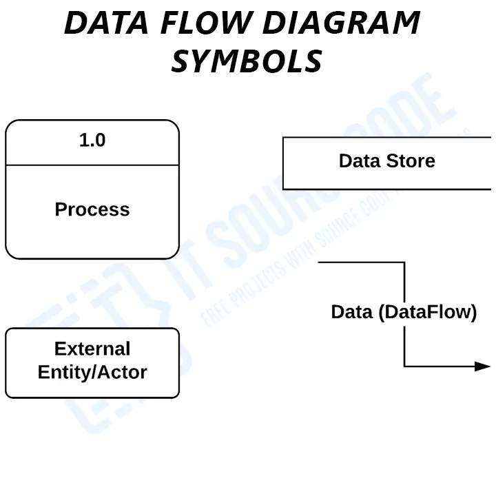
- External Entities are the entry and exit points for data entering and leaving the system. Entities are referred to as terminators, sources, sinks, and actors.
- The process is the portion of DFD that modifies and generates output from data.
- A Data Store (database) is a table that stores the files or repositories for future use.
- Data Flow is the flow of data between external entities, processes, and data stores.
Hospital Management System Context Diagram
The context diagram (DFD level 0) shows the system’s overall function in a single process. It is used to pinpoint the very purpose of the hospital management system.
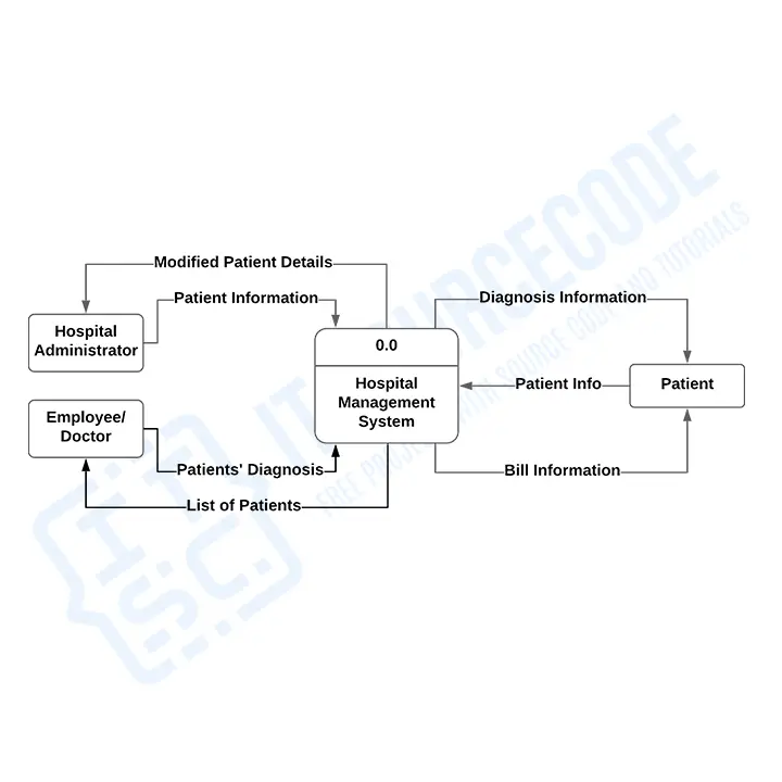
The sample context diagram highlights the main process which is hospital management.
To invoke the main function, the users (external entities) will provide inputs. Its external entities were the admin, patient, and employee (doctors & nurses).
The flow of data then starts as soon as the input is present. The following diagrams will expound on the idea of the hospital system’s context diagram.
1st Level DFD for Hospital Management System
1st level of the (DFD) data flow diagram shows more emphasis on the concept of a context diagram. This level is considered the expanded version of the previous diagram.
DFD level 1 example:

This example shows the sub-processes of hospital management. These sub-processes comprise the important functions of the system which complete the whole project.
Hospital Management System Sub-processes:
- Patient Management
- Assigning Room or Facility
- Assigning Medicine
- Employee (Doctor and Nurses) Management
These processes specify the paths (flows) of data that may enter and exit the system.
Note:
The data inputs and outputs as well as the system’s sub-processes are based on the basic concept of hospital management.
Each of these can be changed depending on your project needs. In some projects, DFD levels 0 and 1 are enough to explain the system function.
However, if your project needs more explanation or emphasis, you may include the DFD level 2.
2nd Level DFD for Hospital Management System
DFD level 2 is the highest abstraction among the data flow diagram levels. It focuses more on discussing the processes of the specific sub-process in the DFD level 1.
In short, this level provides a specific explanation of the specific sub-process.
However, the example diagram below does not contain an illustration of the former level’s concept.
Instead, it highlights the system’s databases in the form of a data store. Know more about the system’s database in Hospital Management System Database Design.

In this example, the databases of the hospital management system are as follows:
- Patient Database
- Medicines Database
- Employee Database
Each of these databases (data store) becomes the storage of data that comes in and the source of data that comes out.
Example:
An input containing the “patient’s information” is passed to the “manage patient” process. During the process, the input will have some changes depending on the “patient’s diagnosis” and “medication” (doctor’s input).
The processed data is then stored in the “patient database”. As a result, the database will produce the “bill information” output for patients.
Remember: The 2nd level of DFD may come in multiple diagrams depending on the sub-processes that you need to specify.
Note: The given examples are based on the general view of the hospital management system. Its ideas can be modified or exchanged to meet the requirements of your project.
Working hospital management source code that implements this diagram
The diagram above defines the flows; these are the actual hospital management systems on itsourcecode.com that implement them. Pick one in your team’s stack and you have a working reference to point your panel at when they ask “show me where this flow actually runs in code.”

PHP: Hospital Management System in PHP
Vanilla PHP + MySQL. OPD, doctor schedule, patient records, billing. Maps directly to the data flows shown above.

Java: Hospital Management System in Java
Java Swing + JDBC + MySQL. NetBeans-ready, perfect for OOP defense.

ASP.NET MVC: Hospital Management System in ASP.NET MVC
C# + SQL Server. Controller boundaries mirror the Level 1 processes in your DFD.
VB.NET: Hospital Information Management in VB.NET
VB.NET + MySQL. Windows Forms UI, ideal if your panel still prefers VS2008-style demos.

Django (Python): Django Hospital Management System
Django 4 + Bootstrap. Class-based views map cleanly to the entities in your DFD.

Laravel (PHP): Online Hospital Management in Laravel
Laravel 9 + Tailwind. MVC + Eloquent ORM mirrors your DFD process decomposition.

CodeIgniter (PHP): Complete Clinic Management in CodeIgniter
CI3 + Bootstrap. Closest analogue when your DFD focuses on outpatient/clinic flows.
How to use this for your Chapter 3 (Methodology): download the project in your stack, then map each process and data store in this diagram to a specific module, controller, or table in the downloaded source. That mapping IS the bridge between your design chapter and your implementation chapter, the single thing panels want to see traced end to end.
Official documentation
Working source code for this system
Download the actual implementation of this system in your preferred language. Each project includes source code, database, and setup instructions for BSIT capstone use.
- PHP: Hospital Management System Project In PHP With Source Code
- VB.NET: Hospital Management System Database Design
- Java: Project On Hospital Management System In Java Source Code
- Python: Django Online Medical Management System with Source Code
- Django: Django Online Medical Management System with Source Code
- Laravel: Clinic Management System Project in Laravel with Source Code
Frequently Asked Questions
What is a DFD for Hospital Management System?
A Data Flow Diagram (DFD) for Hospital Management System is a UML diagram that shows how patient, doctor, appointment, billing, and pharmacy data flows through the hospital system. It documents processes like patient registration, appointment scheduling, medical records management, billing, and pharmacy, essential for capstone projects in healthcare IT.
What are the three levels of Hospital Management DFD?
Hospital Management System DFD has three levels. Level 0 (Context) shows the hospital system with external entities: Patient, Doctor, Nurse, Admin, Pharmacist. Level 1 breaks the system into main processes: Patient Registration, Appointment Management, Medical Records, Billing, Pharmacy, and Reports. Level 2 details each process, for example, Billing into invoice generation, insurance processing, and payment.
What external entities are in Hospital Management DFD?
The external entities in Hospital Management System DFD are: Patient (registers, makes appointments, receives treatment, pays bills), Doctor (records diagnoses, prescriptions), Nurse (administers care, records vitals), Pharmacist (dispenses medication), Admin (manages system, generates reports), Insurance Provider (claims processing), and Lab Technician (records test results).
What data stores are used in Hospital Management DFD?
Hospital Management DFD includes these data stores: D1 Patient Records (personal info, medical history), D2 Doctor Database (specialization, schedule), D3 Appointments (date, time, patient, doctor), D4 Medical Records (diagnosis, treatment), D5 Pharmacy (medicines, stock), D6 Billing (charges, payments), D7 Lab Results (tests, reports), and D8 Insurance Claims.
Where can I download Hospital Management System DFD documentation?
You can download the complete Hospital Management System DFD package including all three levels (0, 1, 2), ER diagram for database design, PHP/MySQL source code, and capstone-ready chapter documentation, all available for free. This package is tested and follows standard UML notation for IT capstone defense preparation.
Conclusion
The DFD (data flow diagram) for the hospital management system project is the visualization of data and business processing.
Each of its levels was defined and discussed for the benefit of understanding the role of DFD levels 0, 1, and 2.
Related Articles
- DFD for Employee Management System
- DFD for School Management System
- Blood Bank Management System DFD
- DFD for Bank Management System
- DFD for Loan Management System
- Doctor Appointment System DFD
Inquiries
If you have inquiries or suggestions about DFD for the Hospital Management System, just leave us your comments below. We would be glad to hear to concerns and suggestions and be part of your learning.

Mary Grace G. Patulada
Programmer & Technical Writer at PIES IT Solution
Mary Grace G. Patulada (pen name ‘Nym’) is a programmer and writer at PIES IT Solution with a BSIT background from Carlos Hilado Memorial State College, Binalbagan Campus. Authored 370+ UML diagram tutorials and capstone documentation guides at itsourcecode.com. Specializes in UML (class, use case, activity, sequence, component, deployment), DFD, and ER diagrams for BSIT capstone projects.
Expertise: UML Diagrams · DFD · ER Diagrams · Use Case Diagrams · Activity Diagrams · Capstone Documentation · PHP · View all posts by Mary Grace G. Patulada →
That’s was amazing but l would like to ask if there will be third and fourth data flow diagrams