

A Payroll Management System Class Diagram is a picture that shows the system’s classes and how they relate to each other.
This UML Class Diagram is made to help programmers build the Employee Payroll management system. It has the class’s attributes, methods, and how classes relate to each other. These contents make sure that the way your Payroll management system is built is in line with what it should do.
Payroll management class diagram design considerations
The payroll management system is software that lets you handle all of your employees’ financial information in an easy and automatic way. This payroll administration system takes care of employees’ wages, deductions, other forms of transportation, net pay, bonuses, and pay stubs.
Payroll processing is the process of making sure that employees get paid based on their type, status, salary, wages, and deductions. It’s also necessary to file reports with customs and pay taxes on wages. At the most important points in processing payroll, there needs to be a checkpoint to make sure nothing goes wrong.
In short, the payroll management process is how a company takes care of its employees’ financial information. The employee’s wages, incentives, bonuses, deductions, and net pay would be listed.
Simple Class Diagram (UML) for Payroll Management System
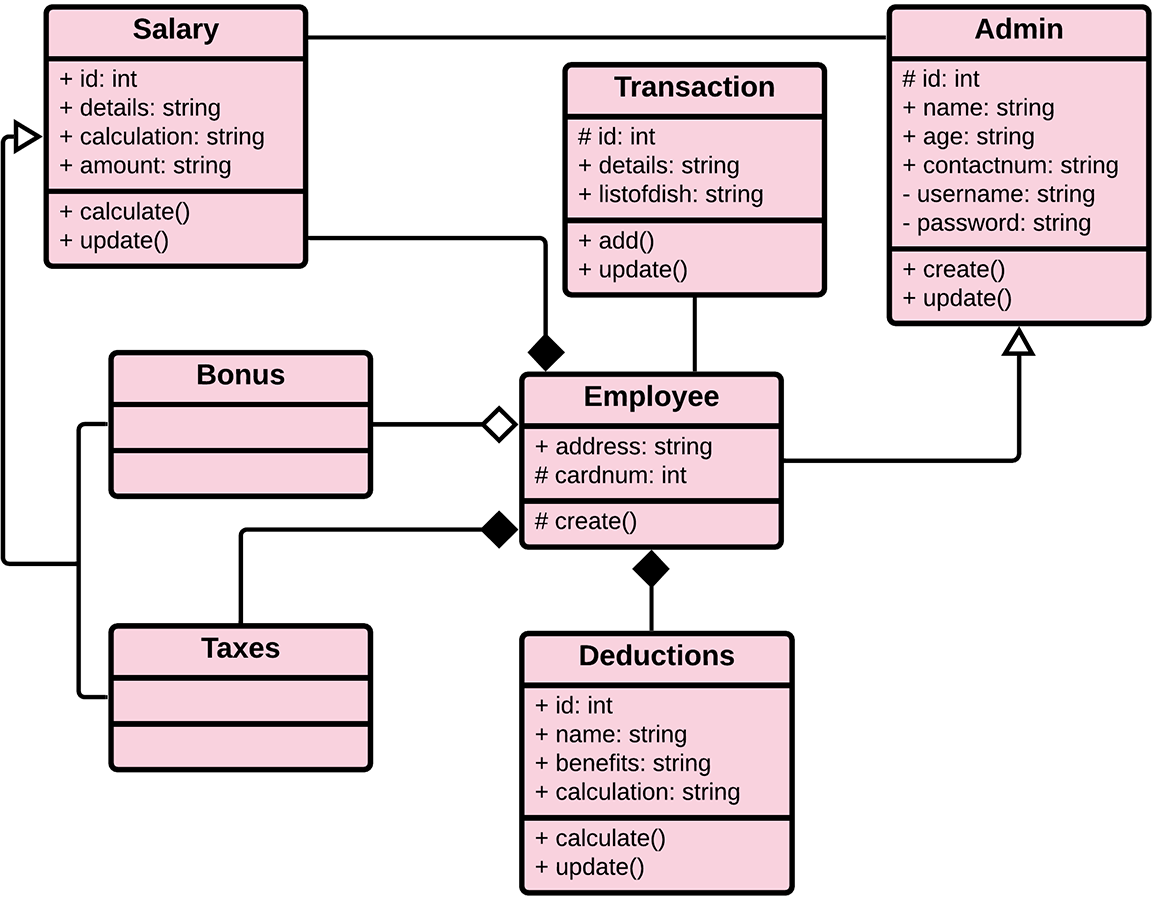
The illustration shown in this article gives you the hint on how will you design your own UML Class Diagram. It has a simple idea of how the class Diagram works.
The classes were determined, which are symbolized by boxes. They were designated with their corresponding attributes and show the class’s methods. Their relationships are also plotted to show the connections between classes and their multiplicity.
You should also look into the visibility symbols displayed in the diagram. These are important because they declare the status of attributes in your class diagram. Some of the classes’ attributes are public (+), which means that they can be accessed by the classes connected to them.
While the protected (#) symbols mean that the attributes of the data can be accessed by the same classes or subclass, the (-) symbol means it cannot be accessed by other classes.
Here is the Class Diagram for Payroll Management System:
Free tool
Generate this Class Diagram in 3 minutes
You have the structure. Now build it with your own entities. The Payroll template comes pre-filled, so you rename what does not match your project and export straight into your Chapter 3.
Open the Payroll template →3 free diagrams every week. No credit card needed.
Student Management System Class Diagram in Java (2026 Code Example)
Below is a complete Java implementation following the Class Diagram structure. You can copy these classes directly into your capstone project as a starting point:
Employee Class
import java.util.ArrayList;
import java.util.Date;
import java.util.List;

public class Employee {
    private String employeeId;
    private String name;
    private String position;
    private double basicSalary;
    private List<Transaction> transactions;

    public Employee(String employeeId, String name, String position, double basicSalary) {
        this.employeeId = employeeId;
        this.name = name;
        this.position = position;
        this.basicSalary = basicSalary;
        this.transactions = new ArrayList<>();
    }

    public void generatePayroll(double bonus, double deduction) {
        double netPay = (basicSalary + bonus) - deduction;
        Transaction transaction = new Transaction(this, new Date(), basicSalary, bonus, deduction, netPay);
        transactions.add(transaction);
    }

    public List<Transaction> getTransactions() {
        return transactions;
    }
}
Transaction Class
import java.util.Date;

public class Transaction {
    private Employee employee;
    private Date payrollDate;
    private double basicSalary;
    private double bonus;
    private double deduction;
    private double netPay;

    public Transaction(Employee employee, Date payrollDate,
                       double basicSalary, double bonus,
                       double deduction, double netPay) {
        this.employee = employee;
        this.payrollDate = payrollDate;
        this.basicSalary = basicSalary;
        this.bonus = bonus;
        this.deduction = deduction;
        this.netPay = netPay;
    }

    public void updateNetPay(double netPay) {
        this.netPay = netPay;
    }
}
Student Management System Class Diagram in PHP (2026 Code Example)
Here’s the same Class Diagram implemented in modern PHP 8.x. This pattern works well for Laravel and CodeIgniter capstones:
Employee.php
<?php

class Employee {
    private string $employeeId;
    private string $name;
    private string $position;
    private float $basicSalary;
    private array $transactions = [];

    public function __construct(
        string $employeeId,
        string $name,
        string $position,
        float $basicSalary
    ) {
        $this->employeeId = $employeeId;
        $this->name = $name;
        $this->position = $position;
        $this->basicSalary = $basicSalary;
    }

    public function generatePayroll(float $bonus, float $deduction): void {
        $netPay = ($this->basicSalary + $bonus) - $deduction;

        $this->transactions[] =
            new Transaction($this, new DateTime(), $this->basicSalary, $bonus, $deduction, $netPay);
    }

    public function getTransactions(): array {
        return $this->transactions;
    }
}
Transaction.php
<?php

class Transaction {
    private Employee $employee;
    private DateTime $payrollDate;
    private float $basicSalary;
    private float $bonus;
    private float $deduction;
    private float $netPay;

    public function __construct(
        Employee $employee,
        DateTime $payrollDate,
        float $basicSalary,
        float $bonus,
        float $deduction,
        float $netPay
    ) {
        $this->employee = $employee;
        $this->payrollDate = $payrollDate;
        $this->basicSalary = $basicSalary;
        $this->bonus = $bonus;
        $this->deduction = $deduction;
        $this->netPay = $netPay;
    }

    public function updateNetPay(float $netPay): void {
        $this->netPay = $netPay;
    }
}
UML Class Diagram Symbols, Complete Reference Table
Use this reference table to read or draw any UML Class Diagram correctly. These symbols are standard across all UML modeling tools:
| Symbol | Name | Meaning |
|---|---|---|
| ― | Association | Solid line , basic “uses” or “knows about” relationship |
| ―◇ | Aggregation | Hollow diamond , weak “has-a” (part can exist without whole) |
| ―◆ | Composition | Filled diamond , strong “contains-a” (part dies with whole) |
| ―▷ | Inheritance / Generalization | Hollow triangle , “is-a” parent/child relationship |
| – – – ▷ | Realization | Dashed line with hollow triangle , interface implementation |
| – – – ► | Dependency | Dashed arrow , temporary “uses” relationship |
| + | Public visibility | Attribute or method accessible from anywhere |
| – | Private visibility | Attribute or method accessible only inside the class |
| # | Protected visibility | Accessible within the class and subclasses |
| ~ | Package visibility | Accessible within the same package (mostly Java) |
| 1, 0..1, 0..*, 1..* | Multiplicity | Cardinality at relationship endpoints (how many instances) |
Quick rule: If you’re unsure between aggregation and composition, ask: “If I destroy the whole, does the part still exist?” Yes = aggregation. No = composition.
How to Draw Payroll Management System Class Diagram, Step by Step
Step 1, Open draw.io
Go to app.diagrams.net → create blank diagram → enable UML shapes.
Step 2, Draw Employee class
Employee
- employeeId: String
- name: String
- position: String
- basicSalary: double
Methods:
- generatePayroll(bonus: double, deduction: double): void
- getTransactions(): List
Step 3, Draw Transaction (Payroll Record)
Transaction
- payrollDate: Date
- basicSalary: double
- bonus: double
- deduction: double
- netPay: double
Method:
- updateNetPay(netPay: double): void
Transaction represents a payroll record per employee.
Step 4, Draw relationships
- Employee → Transaction (1 to 0..*)
- Transaction → Employee (association back reference)
No need for a third class because payroll is a direct employee-based computation.
Step 5, Add multiplicity
- Employee: 1 → Transactions: 0..*
- Transaction: 1 → Employee: 1
Step 6, Export
- PNG (minimum 1200px width)
- PDF for documentation
💡 Pro tip: draw.io is completely free and our top pick. If you need more advanced features (auto-layout, version history, team collaboration), Lucidchart has a powerful UML tool with a free tier that’s sufficient for most capstone projects.
Common Mistakes in Payroll Management System Class Diagrams
Mistake #1, Treating payroll as just calculation logic
Payroll is not only computation; each payroll run is a Transaction (record entity) that must be stored.
Mistake #2, Missing multiplicity
Always include:
- Employee 1 → 0..* Transactions
Missing labels = incomplete UML.
Mistake #3, Mixing database schema with UML
Do NOT use:
- employee_table
- payroll_tbl
Use object names only:
- Employee
- Transaction
Mistake #4, No separation between salary components
Students often store only netPay.
Correct design includes:
- basicSalary
- bonus
- deduction
- netPay
Mistake #5, Wrong assumption that Transaction belongs to Employee
Transaction does not “belong” permanently; it represents a payroll event record.
Use association, not composition.
Mistake #6, Low-quality diagram export
Always export:
- PNG ≥ 1200px
- PDF for submission
Blurry payroll figures can hurt defense clarity.
Aside from that, you can learn more about Diagrams by reading the linked and suggested articles below.
- Payroll Management System UML Diagrams
- Employee Payroll System Class Diagram
- Activity Diagram for Payroll Management System
Conclusion
The Payroll Management System Management System is a modeled diagram that explains its classes and relationships. The diagram shows the names and attributes of the classes, as well as their links and their methods.
It is the most essential type of UML diagram, which is critical in software development. It is an approach to show the system’s structure in detail, including its properties and operations.
Inquiries
Now let me ask you something. What have you learned through the discussion? May this article help you with your projects in the future?
If you have inquiries or suggestions about Payroll Management System Class Diagram | UML just leave us your comments below.
Keep us updated and Good day!
Working payroll management source code that implements this diagram
The diagram above defines the flows; these are the actual payroll management systems on itsourcecode.com that implement them. Pick one in your team’s stack and you have a working reference to point your panel at when they ask “show me where this flow actually runs in code.”

PHP: Payroll Management System in PHP
Vanilla PHP + MySQL. Employee, Salary, Deduction, Payslip classes map 1:1 to MySQL tables.

Java: Payroll Management in Java NetBeans
Java Swing + JDBC + MySQL. Each UML class becomes a .java file with constructor + getters/setters.
VB.NET: Payroll System in VB.NET
VB.NET + MySQL. Windows Forms with one form per UML class entity.
ASP.NET: Payroll Management in ASP.NET
C# + SQL Server. EF model classes mirror your UML, ideal for Microsoft-track schools.

Django (Python): Payroll Management in Django
Django 4 + Bootstrap. Django models = your UML class diagram in Python form.
How to use this for your Chapter 3 (Methodology): download the project in your stack, then map each process and data store in this diagram to a specific module, controller, or table in the downloaded source. That mapping IS the bridge between your design chapter and your implementation chapter, the single thing panels want to see traced end to end.
Official documentation
Working source code for this system
Download the actual implementation of this system in your preferred language. Each project includes source code, database, and setup instructions for BSIT capstone use.
- PHP: Payroll Management System Project in PHP with Source Code
- VB.NET: Breadline Payroll Management System using VB.net
- Java: Payroll Management System Project in Java NetBeans
- Python: Payroll Management System Project in Django with Source Code
- Django: Payroll Management System Project in Django with Source Code
- Laravel: Payroll Management System Project in Laravel With Source Code
Frequently asked questions
What is a class diagram used for in BSIT capstone?
A class diagram shows the static structure of the system: classes, attributes, methods, and relationships (inheritance, association, aggregation, composition). It goes in Chapter 3 of the capstone documentation and communicates the object-oriented design of the system.
What tool should I use to draw the class diagram?
Free options: draw.io (browser-based, saves to Google Drive), Lucidchart free tier, PlantUML (text-based, version-controllable), StarUML (30-day trial then reduced feature set), Visual Paradigm Community Edition. Paid options: Microsoft Visio, Lucidchart pro, Enterprise Architect. For BSIT capstones, draw.io is the most commonly used free tool.
How detailed does the class diagram need to be for capstone defense?
Panel members expect the diagram to match the actual system implementation. Include every major class/use case/entity relevant to the system. Omit trivial helper classes. Every diagram element should have a clear justification. Aim for 1-2 diagrams that fully cover the system, not many partial ones.
Should I use black-and-white or colored diagrams?
Black-and-white is standard for capstone documentation to match the thesis format. Use color only if it improves clarity (e.g., grouping subsystems). Ensure text is readable at printed size (10pt minimum for labels).
Where does this diagram go in the capstone documentation?
Chapter 3 (System Design and Methodology) typically holds all UML diagrams. Introduce each diagram with a 1-paragraph description explaining what it shows and how to read it. Reference specific elements in the surrounding text so panel members can follow the design rationale.

Mary Grace G. Patulada
Programmer & Technical Writer at PIES IT Solution
Mary Grace G. Patulada (pen name ‘Nym’) is a programmer and writer at PIES IT Solution with a BSIT background from Carlos Hilado Memorial State College, Binalbagan Campus. Authored 370+ UML diagram tutorials and capstone documentation guides at itsourcecode.com. Specializes in UML (class, use case, activity, sequence, component, deployment), DFD, and ER diagrams for BSIT capstone projects.
Expertise: UML Diagrams · DFD · ER Diagrams · Use Case Diagrams · Activity Diagrams · Capstone Documentation · PHP
· View all posts by Mary Grace G. Patulada →