This article will enlighten you about What is a Sequence Diagram. It comes with examples to give you clear explanation of UML Sequence Diagram definition and notations.
You’ll be able to know the Sequence Diagram Symbols and How to create it with this tutorial.
You must be informed that the sequence diagram is one of the UML’s (Unified Modeling Language).
The UML is a general-purpose, developmental modeling language used in the field of software engineering to give a common way to depict a system’s architecture.
The primary goal of UML is to establish a standard for visualizing the design of a system.
It’s very similar to plans used in other engineering professions. UML diagrams are used to depict a system’s behavior and structure.
What is a Sequence Diagram?
SEQUENCE DIAGRAM – is also called as system sequence diagram and it depicts object interactions in order.
It displays the scenario’s, objects and the messages that must be passed between them to carry out the functionality. You will know the behavior of your project by designing a sequence diagram.
UML Sequence diagram is one of the important design that must be present in a project development. That is because the UML sequence diagram has the needed illustration in terms of the system behavior.
Though there are a lot of UML Diagram that could show the behavior of a system but they are also unique in different ways.
That is why every Proposed Capstone Project must have a Sequence Diagram that will explain the System Structure and Behavior.
In order for you to create UML Sequence Diagram, you must familiarize first its symbols and notations.
These symbols and notation will help you in designing the sequence diagram. These will also guide you how to emphasize the interaction of the users towards the system and vice versa.
Basic Symbols and Notations used in UML Sequence Diagram:
UML Sequence diagram symbols and notation presented here will guide you in your project development journey. It also comes with explanation and examples to make sure that you’ll understand it better.
Here are the symbols and notations used to design a Sequence Diagram. They were given meaning according to their role in the system’s sequence diagram illustration.
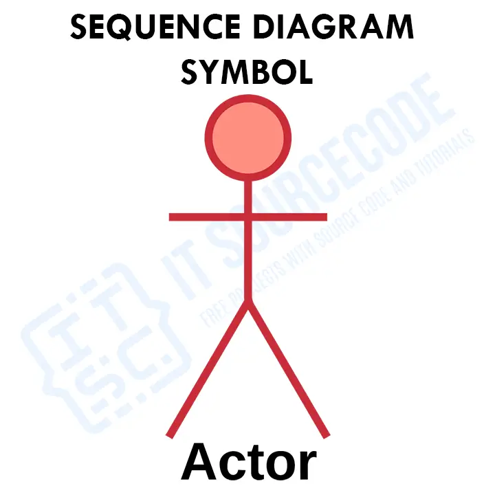
- Actor

Actors are entities that interact with the system while remaining external to it. They were represented by stick figures which serves as a symbol of a user in the UML sequence diagram. The system events that the actors generate in the sequence are referred to as events.
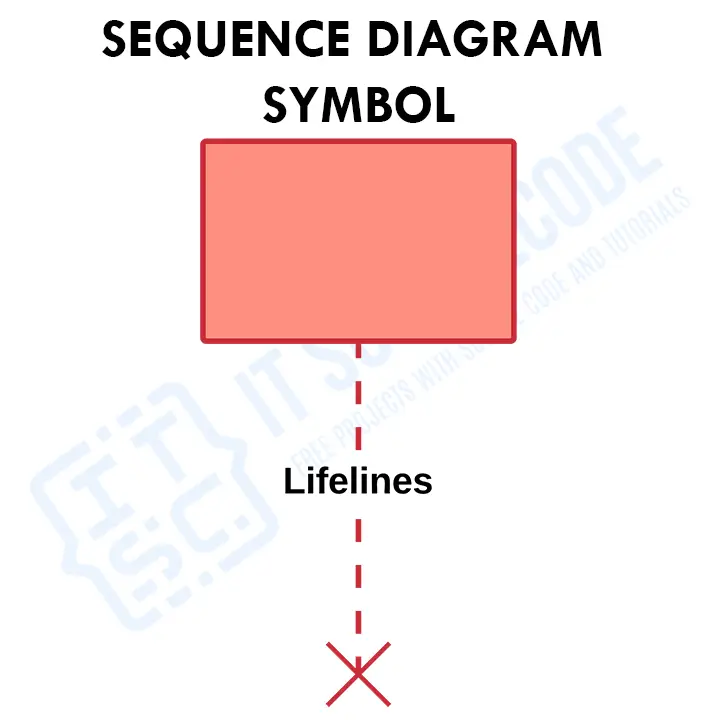
Example of these actors are the users of a certain proposed project. The successive events that occur to an object during the charted process are shown by this dashed vertical line. A named rectangular shape or an actor UML sequence diagram symbol is used to start a lifeline. - Lifeline
A lifeline is a dashed line that indicates events in Sequence Diagram. A named or labeled rectangular shape symbol may be used to start a lifeline.
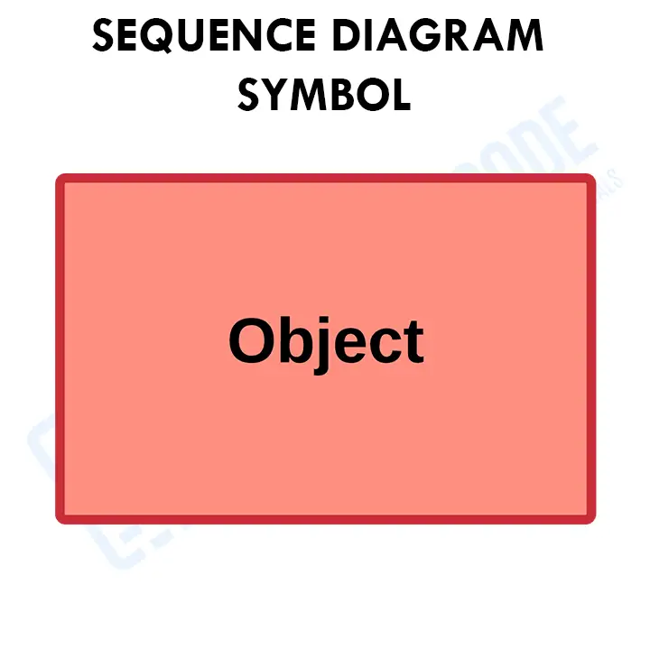
In UML sequence diagram, a lifeline symbol is plotted to let the messages flow through it. This symbol represents an object’s existence at a specific point in time in the modeled UML sequence diagram. As long as the messages passes, then the lifeline of the object still goes on. - Objects
An object in UML sequence diagram is represented by a rectangle with the symbol name or label. The object name or the class name can be used to name an object (anonymous object). It depicts how an object will interact with the rest of the system. This shape should not include any class attributes.
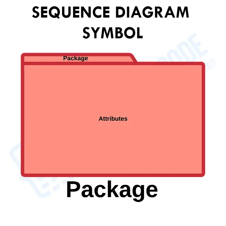
The objects that the system requires or need are all included in designing a UML Sequence diagram are displayed by this symbol. They will also have their lifelines according to how long their functions would last. As long as they were needed for the specific process, then they will be present in the designed diagram. - Package
Entities that interact with or external to the system are displayed here. In UML Sequence diagram 2.0 notation, this symbol is used to include interactive sequence diagram elements. This rectangular form, often known as a frame, features a small inner rectangle for labeling the diagram.
The interactive aspects of the diagram are represented by a package symbol. The Package, like items, is displayed in a rectangular shape, but it has an inner rectangle that is used to name the diagram.
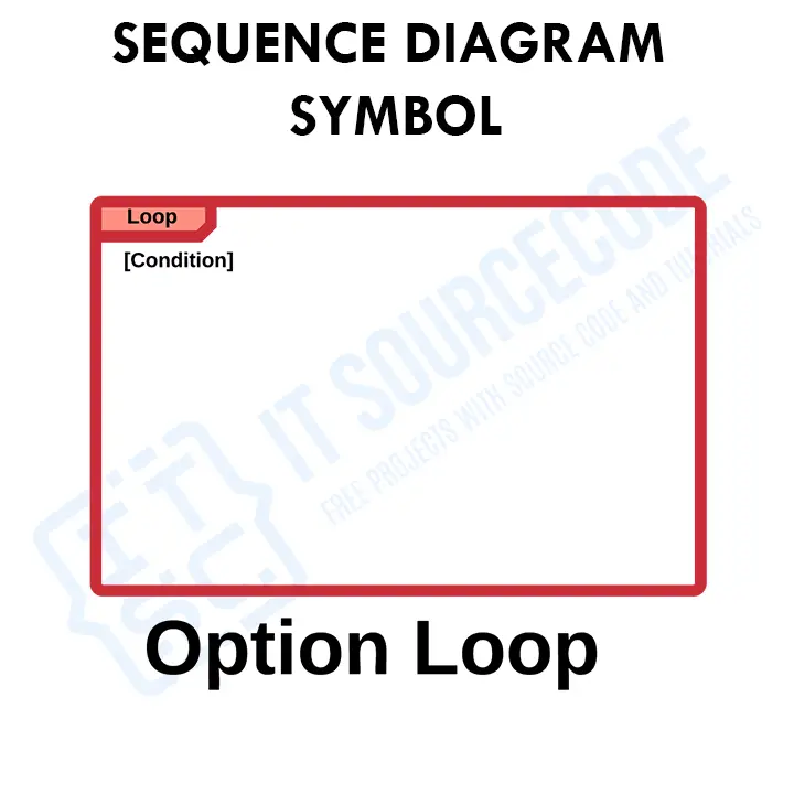
This symbol is used to determine the entities interacts with system. The readers will then understand that there are entities that may interact with the system externally. Not really included but has a part. - Option Loop
The UML Sequence Diagram Option Loop Symbol is used for Modeling if/then situations. A situation that will only happen if specific circumstances are met.
It signifies that there’s a certain process in a system that needs to be repeated until the desired outcome is met. By using this symbol in designing a sequence diagram, reader will be informed that the system includes a loop function in the system.
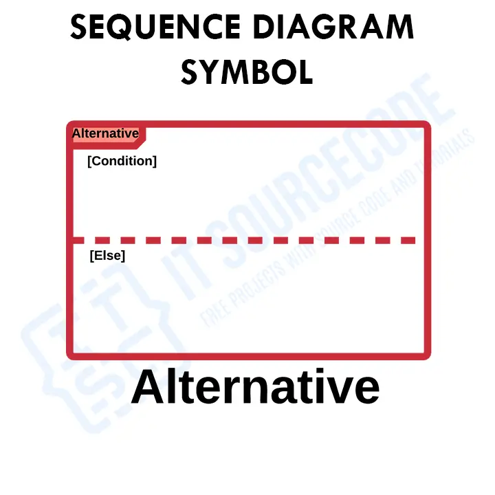
The word opt is used to describe a workflow phase that is optional. For example, in a designed UML sequence diagram, you could use this symbol to emphasize a consequence once a certain option is chosen. - Alternative
To indicate conditional flow in UML sequence diagram, an alternate combined fragment is utilized. It is used to specify an area of a set of lifelines or actors. It also models the if-then-else or conditional logic.
It symbolizes a decision between two or more message sequences (which are frequently mutually exclusive). You can use the designated rectangle shape with a dashed line within to represent options. It will be used as a symbol that there will be consequences between alternative decisions. The decisions may be based on the user or the system.
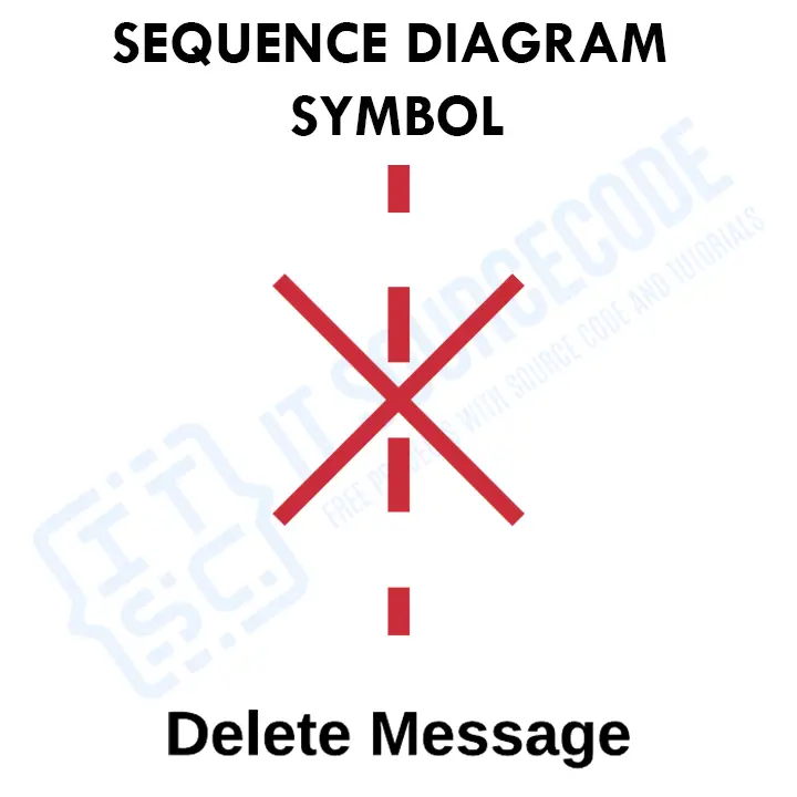
Readers and programmers will be guided that there should be an alternative functions in the system using this UML sequence diagram symbol. - Delete message symbol
To delete an object, use the Delete Message symbol. An “X” is added to the end of an arrow to symbolize this. This message causes an object to be destroyed.
This symbol indicates that the role of an actor or an object has ended in the whole process. Through this symbol, programmers will know the limitations or how long the included participants will only be usable. They will then apply the idea in the system development. - Messages
Messages sent from element to element are used to depict workflow or activity across time in UML sequence diagrams. These Messages are related to the operations and behavior of the Class or objects.
Messages are represented as labeled arrows in UML diagrams, with the arrowhead identifying the call’s direction. The name of the method being called on the receiving object is specified in the text associated with a message when it is sent to an object.
In a UML sequence diagram, a message symbol identifies the type of communication as well as the sender and receiver. Messages can be given any name they like to represent the interaction. A message can be classified as synchronous call, asynchronous call, asynchronous signal, or reply, depending on the type of action it represents.
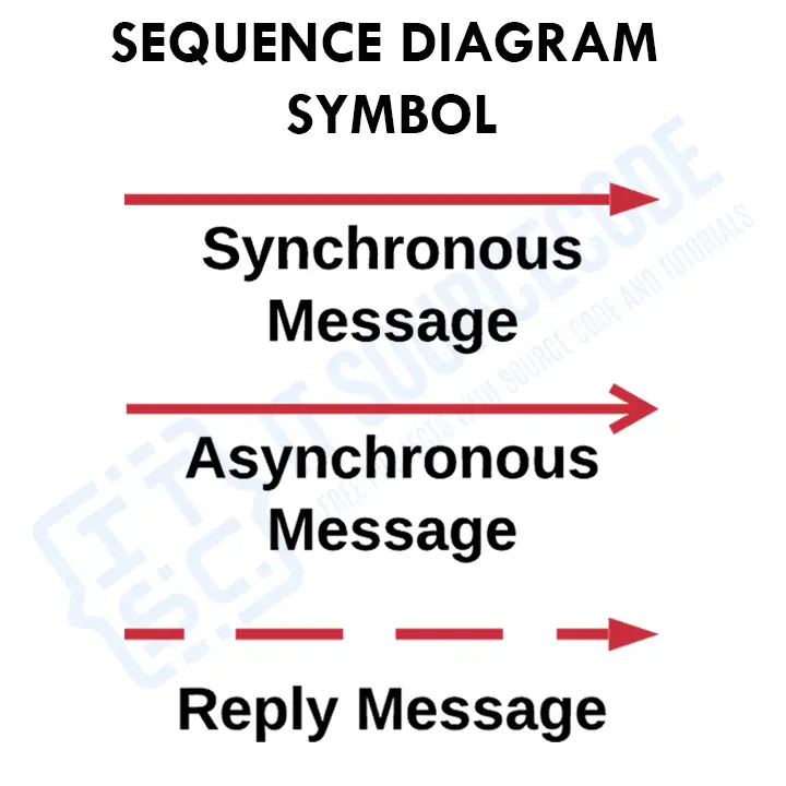
Sequence Diagrams Symbols that Indicates Messages
- Asynchronous message symbol: A solid line with a lined arrowhead is used to represent this. The sender of asynchronous communications does not need to wait for a response before proceeding. In the diagram, only the call should be included. This message is one that does not wait for the recipient to respond. Whether the receiver processes the previous message or not, the contact continues.
- Synchronous message symbol: A solid line with a solid arrowhead is used to represent this. When a sender must wait for a response to a message before proceeding, this symbol is used. Both the call and the response should be depicted in the diagram. Before the interaction may continue, a synchronous message waits for a response. The sender waits until the receiver has finished digesting the message before sending it.
- Reply message symbol: These messages are represented by a dashed line with a lined arrowhead and it responses to calls. A dotted line and an open arrowhead point back to the original lifeline in a reply message. A message sent by an item to itself, typically represented by a U-shaped arrow pointing back to itself.
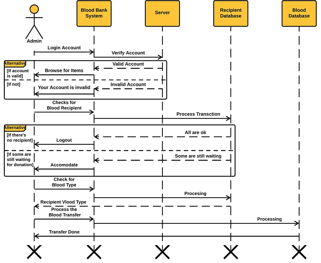
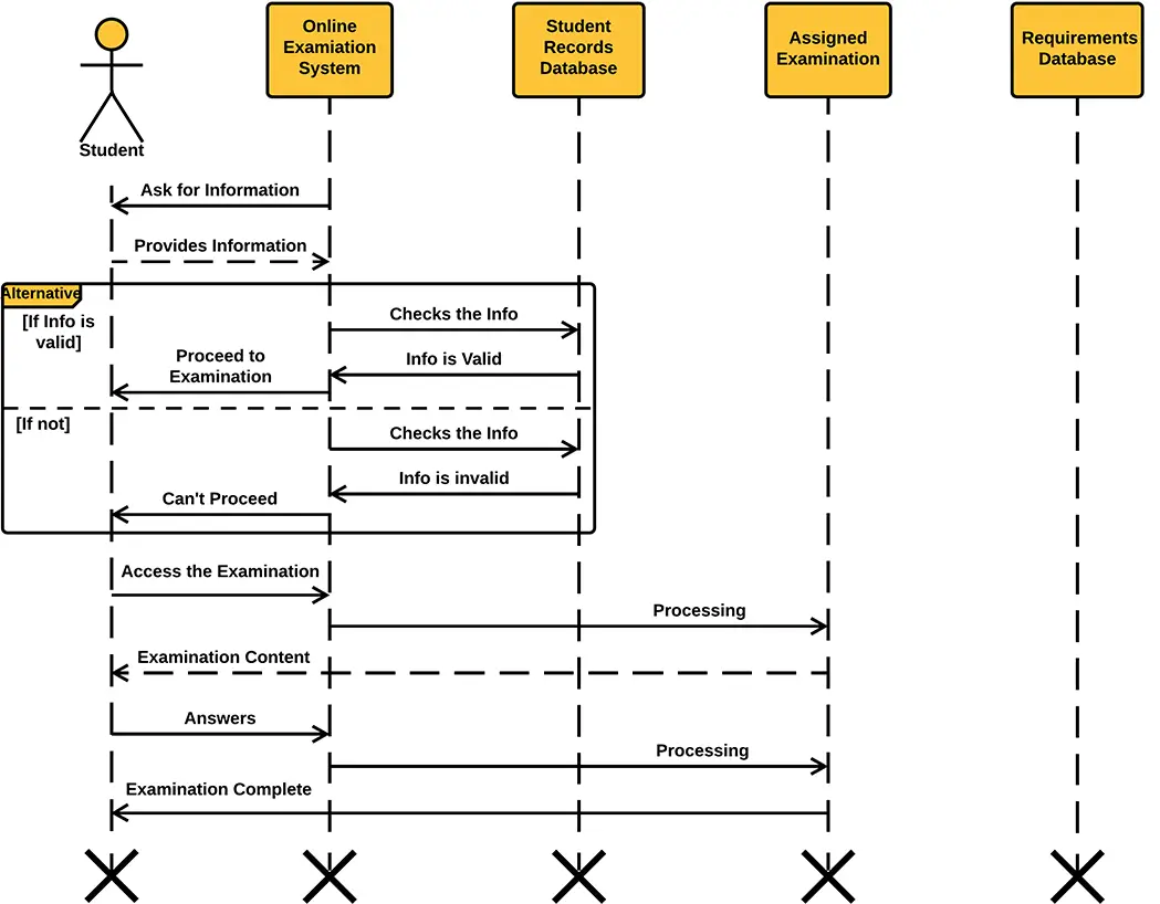
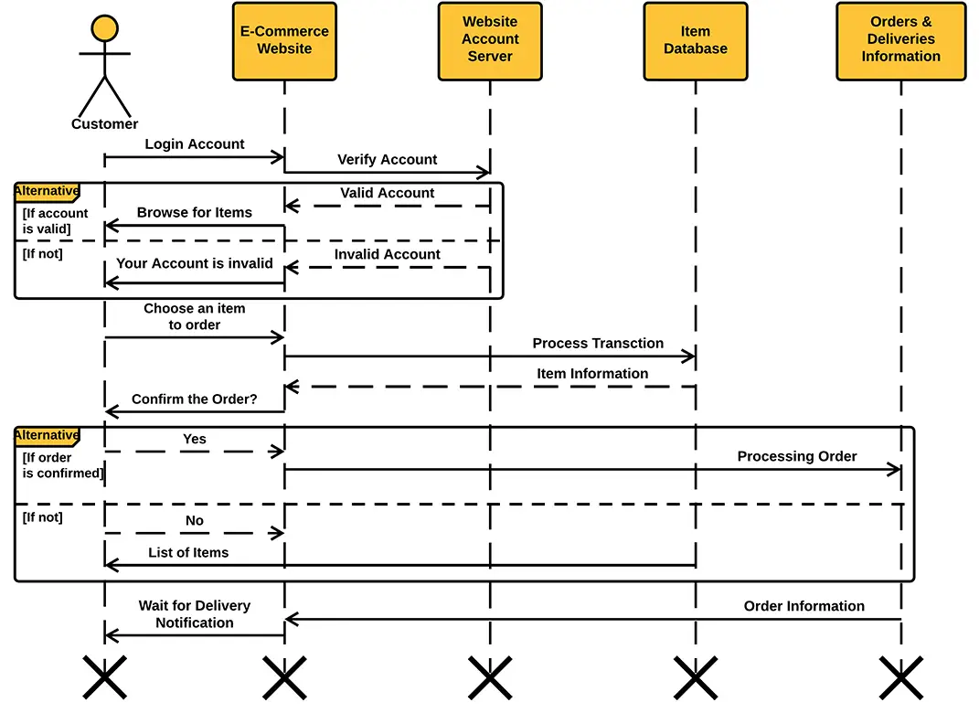
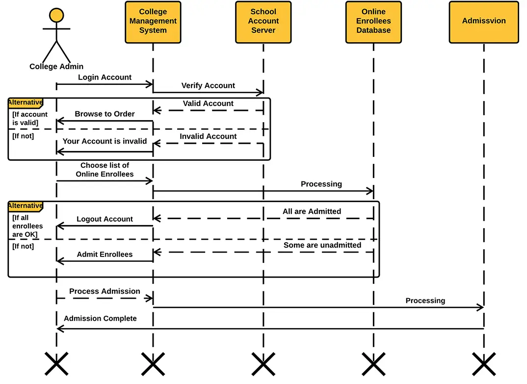
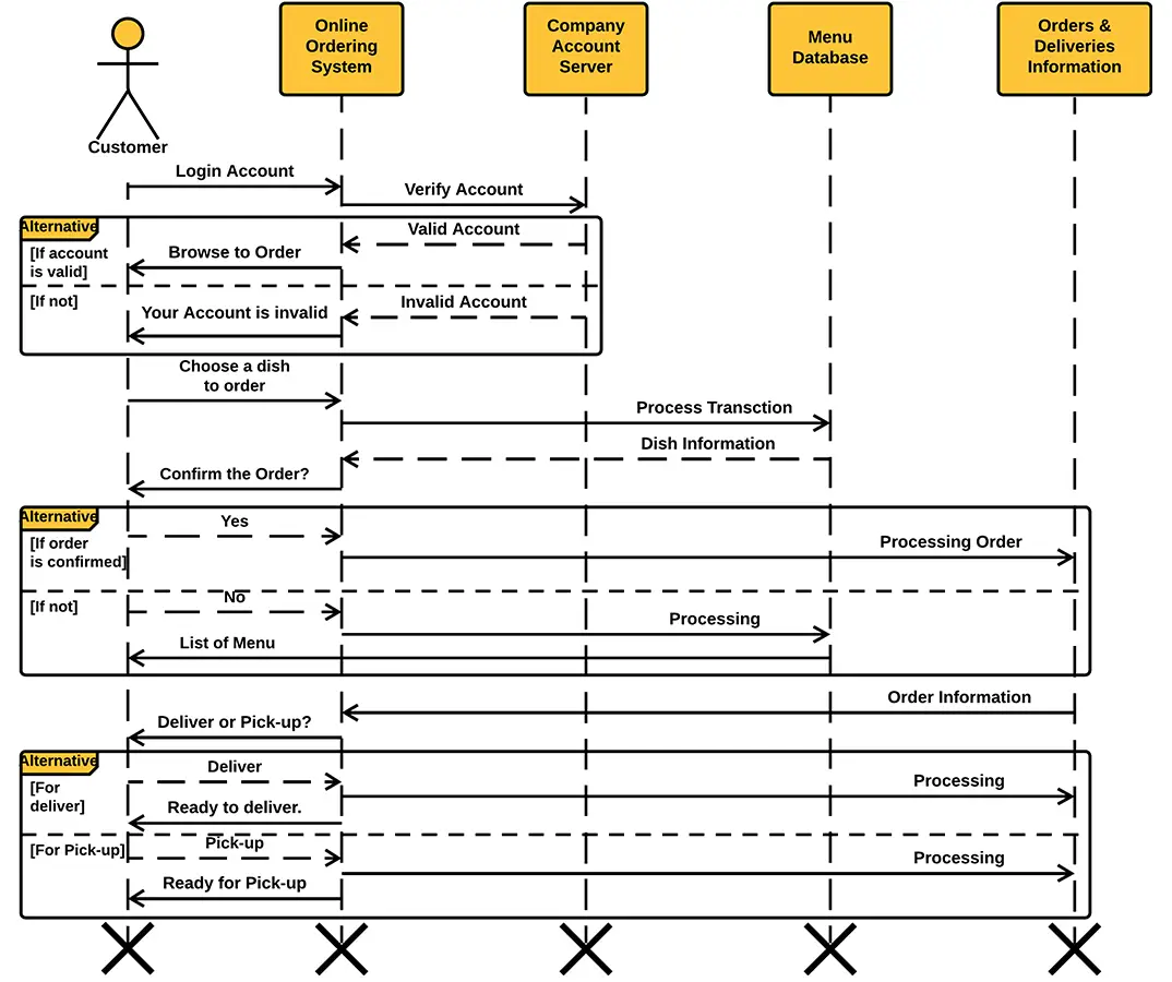
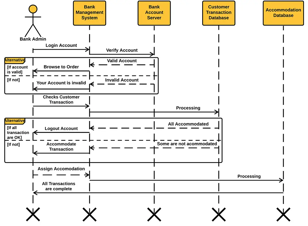
UML Sequence Diagram Examples:
Conclusion
That completes our discussion about What is UML Sequence Diagram: Guide with Examples Itsourcecoders.
I hope that this article helped you a lot. Not just by defining the UML Sequence Diagram but also on how to create it with the given examples and explanation.
Through the given UML Sequence Diagram Symbols, Examples and definition, you can start creating and design the UML Sequence diagram for your project. You can use all the information given in this article and apply it to your project development.
Inquiries
If you have any questions about the How to create and write a Capstone Project chapters, you can ask us through the contact page or leave your comment below.
Keep us updated and have a good day!
Related Article Below
- What is Python Programming Language?
- List of Best Python Libraries for Programmers
- Best Python Course Online | Python Course Free
- Python Compiler Online and Offline
- Free Python Certification | Which and How to Get Best Python Certification
- Best Python IDE for Windows, Linux, Mac OS
- List of Python Interpreters | Guide to Best Python Interpreter Online
- List of Best Python Frameworks 2021 |For Mobile & Software Development
- Best Python Projects for Beginners
- Best Python Projects With Source Code 2021
- How To Make A Point Of Sale System In Python
- Python PIP Command Set-up / Fix: Step by Step Guide
- Student Management System Project in Python with Source Code
- Hotel Management System Project in Python With Source Code
Recommended Articles From the Author
- Best Java Projects With Source Code For Beginners Free Download
- Code For Game in Python: Python Game Projects With Source Code
- Best PHP Projects With Source Code Free Download
- Best Final Year Project in Computer Science
- Final Year Project For Computer Engineering
- Best Final Year Project in Computer Science
- List of VB.Net Projects with Source Code Free Download
- DBMS Mini Projects Topics for Students
- Data Flow Diagram With Examples
- List of Arduino Projects for Beginners
Official documentation
Frequently asked questions
What is a sequence diagram used for in BSIT capstone?
A sequence diagram shows how objects interact over time to accomplish a specific use case: the messages, calls, and return values in chronological order. It complements the use case and class diagrams in Chapter 3.
What tool should I use to draw the sequence diagram?
Free options: draw.io (browser-based, saves to Google Drive), Lucidchart free tier, PlantUML (text-based, version-controllable), StarUML (30-day trial then reduced feature set), Visual Paradigm Community Edition. Paid options: Microsoft Visio, Lucidchart pro, Enterprise Architect. For BSIT capstones, draw.io is the most commonly used free tool.
How detailed does the sequence diagram need to be for capstone defense?
Panel members expect the diagram to match the actual system implementation. Include every major class/use case/entity relevant to the system. Omit trivial helper classes. Every diagram element should have a clear justification. Aim for 1-2 diagrams that fully cover the system, not many partial ones.
Should I use black-and-white or colored diagrams?
Black-and-white is standard for capstone documentation to match the thesis format. Use color only if it improves clarity (e.g., grouping subsystems). Ensure text is readable at printed size (10pt minimum for labels).
Where does this diagram go in the capstone documentation?
Chapter 3 (System Design and Methodology) typically holds all UML diagrams. Introduce each diagram with a 1-paragraph description explaining what it shows and how to read it. Reference specific elements in the surrounding text so panel members can follow the design rationale.

Mary Grace G. Patulada
Programmer & Technical Writer at PIES IT Solution
Mary Grace G. Patulada (pen name ‘Nym’) is a programmer and writer at PIES IT Solution with a BSIT background from Carlos Hilado Memorial State College, Binalbagan Campus. Authored 370+ UML diagram tutorials and capstone documentation guides at itsourcecode.com. Specializes in UML (class, use case, activity, sequence, component, deployment), DFD, and ER diagrams for BSIT capstone projects.
Expertise: UML Diagrams · DFD · ER Diagrams · Use Case Diagrams · Activity Diagrams · Capstone Documentation · PHP · View all posts by Mary Grace G. Patulada →