
What is an Online Food Ordering System Deployment Diagram?
A deployment diagram for online food ordering system is used to describe the system’s operation showing the hardware and software components that run in each node, explaining the connections between them.
Online Food Ordering System Deployment Diagram: Table of contents
- What is an Online Food Ordering System Deployment Diagram?
- Deployment Diagram for Online Food Ordering System: Content
- Food Ordering System Deployment Diagram Description
- Deployment Diagram for Online Food Ordering System
- Online Food Ordering System UML Deployment Diagram (Explanation)
- Deployment Diagram for Food Ordering System (PDF)
- UML Deployment Diagram for Food Ordering System
- Steps in Developing Food Ordering System Deployment Diagram
- Conclusion:
- Recommended Articles from the Author:
- Inquiries
Deployment Diagram for Online Food Ordering System: Content
The table shows the basic details of the deployment diagram of the online food ordering system. It has quick description details of the project.
| Name: | Online Food Ordering System Deployment Diagram |
| Abstract: | The Online Food Ordering System Deployment Diagram represents the physical structure of the project. It reveals the software and hardware included for the application to work correctly. |
| UML Diagram: | Deployment Diagram |
| Users: | Food Stand or Restaurant Admin, Crews, and Customers. |
| Tools Used: | Diagraming Tools that have UML Deployment Diagram Symbols |
| Designer: | ITSourceCode.com |
Food Ordering System Deployment Diagram Description
The designed food ordering system deployment diagram initiates the process when a consumer looks for a preferred restaurant or food stand. This process is usually categorized by cuisine, and ordered from a menu of available dishes, with the option of delivery or pick-up. Payment can be made in a variety of ways and remits a portion of the proceeds to the online food delivery service.
The whole process includes links that serve as the source and storage of the data (information). These links are the software and hardware used as channels of data to carry out the process. The links are associated with connections to properly describe the paths and destinations of users’ requests.
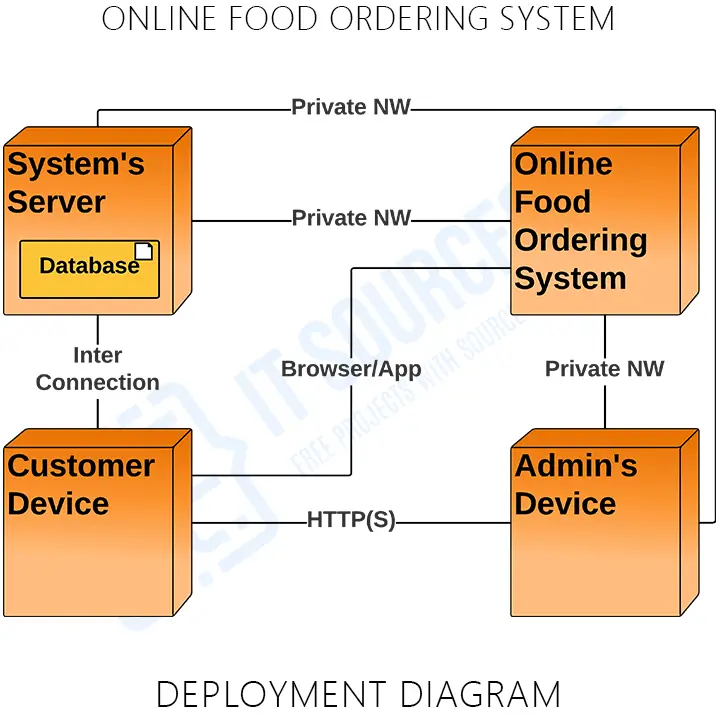
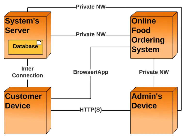
Deployment Diagram for Online Food Ordering System
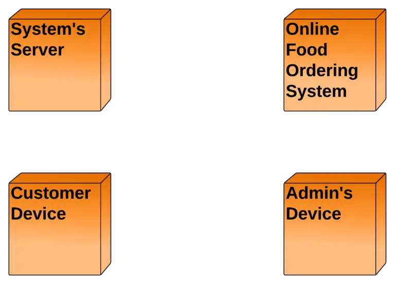
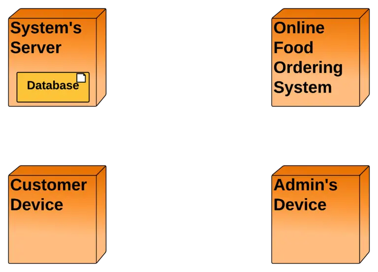
The nodes included in the online food ordering system deployment diagram are represented by boxes. These boxes are labeled as software or hardware that specifies the included components to carry out the food ordering process. The boxes will then be connected and labeled to declare the type of connection they have with the other components.
An online food ordering system is a piece of software that allows restaurants, coffee shops, and bars to take orders over the internet. It usually allows customers to select and pay for food before informing the kitchen that an order has been placed. This occurs without any interaction between employees and customers.
Online Food Ordering System UML Deployment Diagram (Explanation)
The Online Food Ordering System UML deployment diagram explains the sketch of the relationship between software and hardware. These hardware and software are labeled to clarify their part in the system’s operation. They were represented by nodes and the connections were represented by labeled arrows.
The deployment diagram shows the scenario when the system is deployed. It has 4 nodes represented with boxes and relationship connections. The nodes are the online food ordering system, the customer’s device, the admin’s device, and the database (system server). The system server node contains a developed database that will hold the details of the system online.
For the connection, the system is connected to the server database using a private network which enables it to pass a connection to the devices and enable users to access the system and database. The admin and the customer then can communicate using an online or internet connection.
Deployment Diagram for Food Ordering System (PDF)
You may download the Deployment Diagram for Online Food Ordering System PDF by clicking the button below. It has the full details and discussion on System’s Deployment Diagram. You can also modify its content to complete your project requirements and needs.
UML Deployment Diagram for Food Ordering System
A deployment diagram for the food ordering system in UML is used to illustrate its’ physical architecture. In UML, deployment diagrams can show you how the software and hardware of the learning system work together and where the processing takes place.
The food ordering system uses a UML deployment diagram to show how should the developed software be deployed. It clarifies the communications between links(nodes) which helps the project to work according to the design given to it. Deployment diagrams depict the setup of run-time processing nodes and the components that reside on them.
Steps in Developing Food Ordering System Deployment Diagram
Time needed: 10 minutes
Here are the steps in developing the food ordering system deployment diagram.
- Determine the diagram’s purpose.
To determine the purpose of the deployment diagram, know the description of the online food ordering system. The purpose of the deployment diagram is to design the needed components (software and hardware) of the system. This is to support and imply the whole processes when the online food ordering system operates.
- Add the diagram’s nodes.
The term “node” refers to the physical devices that make up the system. Artifacts are deployed on these nodes. Node instances on which artifact instances will be implemented are also possible.

The essential software or hardware elements, or nodes, in the system are represented by the three-dimensional boxes known as nodes. The smaller forms included within the boxes reflect the software artifacts that are distributed, and the lines from node to node indicate relationships. - Add more pieces to the diagram, such as components or artifacts, if needed.
A deployment diagram depicts the locations of components and artifacts in the deployed system. In a software system, artifacts are model elements that reflect physical entities. Executable files, libraries, software components, documents, and databases are examples of physical implementation units.
- Add communication associations.
A communication association (path) is a sort of relationship between nodes in a deployment diagram that indicates how they communicate messages and signals in UML modeling. Deploy relationships in UML show that a certain type of node can be used to deploy a certain type of artifact.

A message or other sort of communication between nodes is indicated by a line called a relation or association.
Additional Knowledge
The topology of the physical components of a system, where the software components are installed, is visualized using deployment diagrams. Deployment diagrams are used to depict a system’s static deployment view. Nodes and their relationships are depicted in deployment diagrams.
The Deployment Model shows how components will be distributed across the system architecture in detail. It contains information about network capabilities, server specifications, hardware requirements, and other aspects of the planned system’s deployment.
Conclusion:
You need to know the diagrams used to design and develop the Online Food Ordering System. That is because you cannot perfectly create a fully-functional system without it. But if you create this deployment diagram, you will know the software and hardware components that the project should possess. Not only that, you will find out the needed specifications and connect them to the other UML Diagrams.
The deployment diagram is used to model the system’s physical architecture. It describes the connections of components between software and hardware system. By completing the Diagrams per module or per process, you will easily achieve your desired system. Check out our Related and Recommended Articles for more Learning and Information.
Related Articles:
- Deployment Diagram for Online Shopping System
- Deployment Diagram for Hospital Management System
- Deployment Diagram for Railway Reservation System
- Deployment Diagram for E-commerce Website
- Deployment Diagram for ATM System
Recommended Articles from the Author:
- Online Food Ordering System UML Diagrams
- Online Food Ordering System Sequence Diagram
- Online Food Ordering System ER Diagram
- Online Food Ordering System Activity Diagram
- Online Food Ordering System Class Diagram
Inquiries
If you have inquiries or suggestions about Deployment Diagram for Online Food Ordering System, just leave us your comments below. We would be glad to hear to concerns and suggestions and be part of your learning.
Keep us updated and Good day!