
University Admission Management System Sequence Diagram
The University Admission Management System Sequence Diagram describes the series of interactions that occur with the objects when performing the system’s process. It is one of the UML models used for presenting the workflow, sequence of messages, and interactions within the admission system.
System Sequence Diagram for University Admission Management: Table of contents
- University Admission Management System Sequence Diagram
- Project Name and Tool used
- What is UML Sequence Diagram?
- What is a University Admission Management system?
- University Admission Management System Sequence Diagram Description
- Sequence Diagram for University Admission Management System (Illustration)
- University Admission Management System Sequence Diagram (Explanation)
- Sequence Diagram for University Admission System Diagram (Pdf)
- Advantages of Sequence Diagram
- Steps in Developing Sequence Diagram
- Additional Knowledge
- Conclusion
- Related Articles:
- Recommended Articles from the Author:
- Inquiries:
Project Name and Tool used
The table shows the overview of an online university admission system sequence diagram. It tells the overall content of the article to let you know what is the discussion all about.
| Name: | University Admission Management System Sequence Diagram |
| Abstract: | The sequence diagram for university admission management system represents the scenario and the messages that must be passed between objects. It’s an interaction diagram that shows how activities are carried out, including when and how messages are sent. |
| UML Diagram: | Sequence Diagram |
| Users: | School Admin and Students |
| Tools Used: | Lucidchart.com was used to create the diagrams but you may use other diagram tool. |
What is UML Sequence Diagram?
In software engineering, the UML sequence diagram depicts object interactions in a sequence of events. This diagram shows the university admission scenario and how they communicate with each other to function correctly.
According to lucidchart.com, a UML sequence diagram helps software engineers and business experts figure out what the project should perform and how to describe a process that is already in place. It’s a form of interaction diagram since it shows how a group of things interacts and in what sequence.
A sequence diagram is a useful tool for documenting a system’s needs and fleshing out its architecture. Because it depicts the interaction logic between the items in the system in the time order in which they occur, the sequence diagram is quite valuable.
What is a University Admission Management system?
A University management system (UMS) is a software solution for universities and schools. It was created for the University and its affiliated institutions to conduct, monitor, and analyze complicated activities such as Automated Admission, Coordinated Examination, and much more.
The software enables universities and educators to manage routine tasks such as campaigning, student enrollment, admissions, student information, teaching staff, attendance, fees, assignments, exams, certification, and other similar tasks. It reduces workload and improves productivity by facilitating communication and data security.
The information given explains how should the University Admission Management system work. These expectation or existing factors must be meet to achieve and develop an excellent university admission management system.
University Admission Management System Sequence Diagram Description
The sequence diagram is used to look at the behavior of multiple objects within the university admission management system. Sequence diagrams are good for showing how objects work together and in what order the events occur. It shows objects that communicate within the processing system, with messages going from them to each other down the process in a certain order.
The university admission system uses a sequence diagram to show how objects interact and how they happen sequentially. This sequence diagram shows how messages move from one object to another in a way that makes sense.
Sequence Diagram for University Admission Management System (Illustration)
The sequence diagram design for university admission system will enlighten you on how should the system or the actor approach each other. This will also teach you on how to develop the system to achieve its desired behavior. This designed sequence diagram can show programmers and readers the sequence of messages between the actor and the objects.
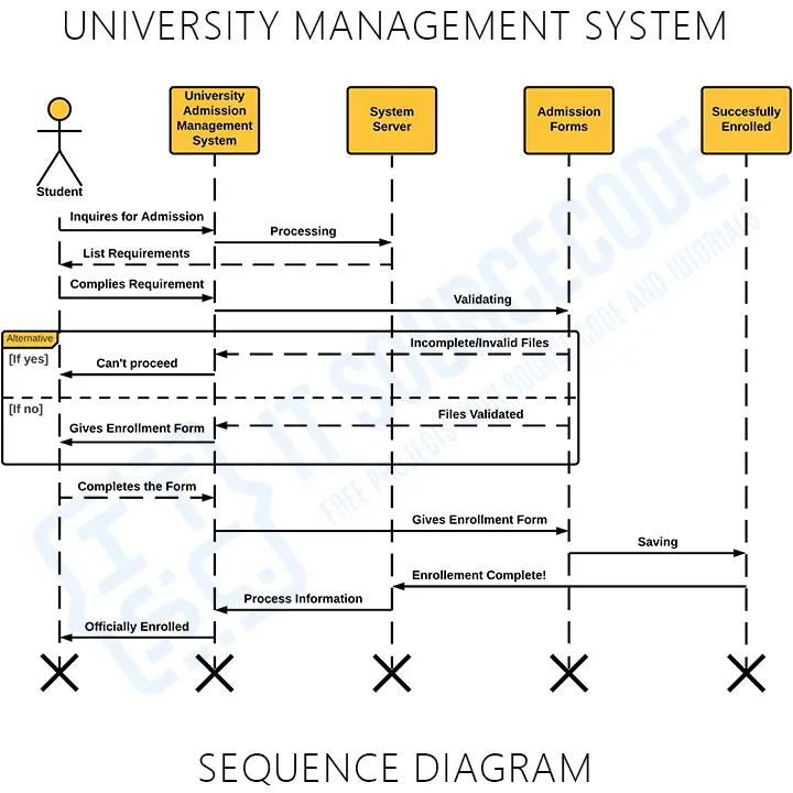
University Admission Management System Sequence Diagram (Explanation)
As you can see through the illustration, the conditions and interactions are emphasized. These interactions are essential for the University Admission Management System development. The series of messages are shown and labeled to guide you in building the System. You can modify the design if you have more ideas. You can also add more features to this design and use it as your project blueprint.
You’ll be able to understand and educate yourself on how the University Admission Management System works by creating a sequence diagram. Because it determines the needed objects, actors, messages, and their interactions.
Sequence Diagram for University Admission System Diagram (Pdf)
You may download the Sequence Diagram for University Admission System PDF by clicking the button below. It has the full details and discussion of the system’s sequence diagram. You can also modify its content to complete your project requirements and needs.
Advantages of Sequence Diagram
The UML sequence diagrams are commonly used by developers to model the interactions between components in a single-use case. They show how the various components of a system interact to perform a function, as well as the order in which the interactions occur when a certain use case is executed. here are the advantages of designing a sequence diagram:
- A sequence diagram depicts the timeline and order in which messages are sent between devices to carry out process functions.
- Sequence diagrams are based on objects rather than classes.
- Used to step-by-step model a system’s process.
- Sequence diagrams are a great way to model the dynamic properties of your system.
- It aids programmers in determining the overall message flow between objects that perform use-case logic.
Steps in Developing Sequence Diagram
Time needed: 10 minutes
Here’s the complete guide and steps in developing and designing your sequence diagram for the university admission management system.
- Finalize the purpose of the project
The first step in doing your sequence diagram is to finalize what your project is all about. The university admission system portrays the idea of registering the student’s information into the course that they want. Then this idea will give you other initiations on what to include in the project.
Take note that you as the developer and your client (if there is one) can decide on what functions and features should be included in your project. It’ll include anything as long as the function or feature is related to the idea of your project. - Place your users or objects
The project users in the sequence diagram will always be based on your targeted users. You can create a design for each of your users or put them all in one design. Just be mindful of having a clear and precise illustration.
The object, on the other hand, is represented by a rectangle with the object’s name underlined. The object name, the object name, and its class, or only the class name can all be used to name an object (anonymous object).
The sequence diagram depicts a group of objects connected by lifelines as well as the messages they exchange over time during the interaction. - Add the lifelines in each user and object
A lifeline represents each instance of interaction. As it moves downhill, it represents the passage of time. Broken vertical lines show the next events that happen to an object during the charted process. A named rectangular shape (object) or an actor symbol is used to start Lifelines.
The lifeline sequence diagram is symbolized by a broken line connected to its head (object) that represents the lifetime of the object. - Structure the sequence of messages (interaction)
A message is a representation of communication between objects or between an object and its surroundings. An event, a triggered operation, or a primitive operation are all examples of messages. A message in the metamodel denotes a certain sort of communication.
In UML diagrams, messages are represented as labeled arrows, with the arrowhead indicating the call’s direction. When a message is sent to an object, the name of the method being called on the receiving object is indicated in the text associated with the message.
In a sequence diagram, a message is a named element that describes one sort of communication between interaction lifelines. The message not only describes the form of communication, but also the sender and receiver. Usually, two things happen the transmitter and the recipient (the points at the ends of messages). - Add alternatives (if needed)
When a scenario needs to choose between two or more message sequences, the alternative combination fragment is employed. It represents the logic of “Otherwise, if. One way for distinguishing which fragment is which “operator for fragments” is to put “alt” in the name box of the frame, also known as the “frame name box.
Different process conditions are denoted by the term “alt. Only one of the options will be implemented. The term “opt” means a workflow phase that can be skipped. - Add the X symbol as the lifeline end
When the object’s lifeline is completed, you can add an X to the end of it to indicate that it has been destroyed. A rectangle represents a recurrence or loop in a sequence diagram.
Additional Knowledge
A sequence diagram is a useful tool for documenting a system’s needs and fleshing out its architecture. Because it depicts the interaction logic between the items in the system in the time order in which the interactions occur, the sequence diagram is quite valuable.
It is a type of interaction diagram that depicts objects as lifelines running down the page, with messages rendered as arrows from the source lifeline to the target lifeline to describe their interactions through time. Complex procedural logic is not intended for sequence diagrams.
Conclusion
The University Admission Management System is a sort of interaction diagram that shows how a group of items interacts and in what order. Software engineers and business experts use these diagrams to understand the requirements of the system or to describe an existing process.
The University Admission Management System must have a designed diagram to define event sequences that will result in a desired outcome. The flow of communication that appears is more important than the message itself. Though the majority of sequence diagrams will show what messages are transmitted and in what order they usually occur.
And that completes our discussion fellas! I hope that this article will help you a lot.
Related Articles:
- Car Rental System Sequence Diagram
- Blood Bank Management System Sequence Diagram
- Online Examination System Sequence Diagram
- E-Commerce Website Sequence Diagram
- College Management System Sequence Diagram
- Online Ordering System Sequence Diagram
Recommended Articles from the Author:
- University Management System UML Diagrams
- University Management System Class Diagram
- University Management System Activity Diagram
Inquiries:
If you have inquiries or suggestions about University Admission Management System Sequence Diagram, just leave us your comments below. We would be glad to hear to concerns and suggestions and be part of your learning.
Official documentation
Working source code for this system
Download the actual implementation of this system in your preferred language. Each project includes source code, database, and setup instructions for BSIT capstone use.
- PHP: Car Driving School Management System in PHP with Source Code
- VB.NET: Enrollment Management System in VB.Net Source Code
- Java: University Management System Project in Java With Source Code
- Python: Django Online College Admission System with Source Code
- Django: Django Online College Admission System with Source Code
- Laravel: School Management System in Laravel With Source Code
Frequently asked questions
What is a sequence diagram used for in BSIT capstone?
A sequence diagram shows how objects interact over time to accomplish a specific use case: the messages, calls, and return values in chronological order. It complements the use case and class diagrams in Chapter 3.
What tool should I use to draw the sequence diagram?
Free options: draw.io (browser-based, saves to Google Drive), Lucidchart free tier, PlantUML (text-based, version-controllable), StarUML (30-day trial then reduced feature set), Visual Paradigm Community Edition. Paid options: Microsoft Visio, Lucidchart pro, Enterprise Architect. For BSIT capstones, draw.io is the most commonly used free tool.
How detailed does the sequence diagram need to be for capstone defense?
Panel members expect the diagram to match the actual system implementation. Include every major class/use case/entity relevant to the system. Omit trivial helper classes. Every diagram element should have a clear justification. Aim for 1-2 diagrams that fully cover the system, not many partial ones.
Should I use black-and-white or colored diagrams?
Black-and-white is standard for capstone documentation to match the thesis format. Use color only if it improves clarity (e.g., grouping subsystems). Ensure text is readable at printed size (10pt minimum for labels).
Where does this diagram go in the capstone documentation?
Chapter 3 (System Design and Methodology) typically holds all UML diagrams. Introduce each diagram with a 1-paragraph description explaining what it shows and how to read it. Reference specific elements in the surrounding text so panel members can follow the design rationale.

Mary Grace G. Patulada
Programmer & Technical Writer at PIES IT Solution
Mary Grace G. Patulada (pen name ‘Nym’) is a programmer and writer at PIES IT Solution with a BSIT background from Carlos Hilado Memorial State College, Binalbagan Campus. Authored 370+ UML diagram tutorials and capstone documentation guides at itsourcecode.com. Specializes in UML (class, use case, activity, sequence, component, deployment), DFD, and ER diagrams for BSIT capstone projects.
Expertise: UML Diagrams · DFD · ER Diagrams · Use Case Diagrams · Activity Diagrams · Capstone Documentation · PHP · View all posts by Mary Grace G. Patulada →