
The UML use case diagram is the behavioral diagram that summarizes activities done in the credit card processing system and its user details. It’s usually depicted as a graphical representation of the system’s behavioral structure.
The credit card processing system use case diagram also known as the UML’s behavioral diagram is composed of processes (use cases) and users or “actors”. It uses defined symbols to describe the overall workflow of the credit card processing system.
Credit Card Processing System Use Case Diagram: Table of contents
- Use Case Diagram for Credit Card Processing System: Details
- What is a Credit Card Processing System?
- Importance of Use Case Diagram for Credit Card Processing System
- Use Case Diagram of Credit Card Processing in Software Engineering
- Credit Card Processing System Design and Implementation
- Use Case Diagram for Credit Card Processing System with Explanation
- Steps in Developing Use Case Diagram for Credit Card Processing System
- Conclusion:
- Related Articles:
- Recommended Articles from the Author:
- Inquiries
Use Case Diagram for Credit Card Processing System: Details
The table shows the quick overview f the use case diagram for credit card processing system. It has the complete details of the project.
| Name: | Credit Card Processing System Use Case Diagram |
| Abstract: | Credit Card Processing System Use Case Diagram defines the context and requirements of the entire system. It is shown using symbols to emphasize the system’s definition. |
| UML Diagram: | Use Case Diagram |
| Users: | Bank Admin or Crews and Credit Card Applicants or Holders. |
| Tools Used: | Any Diagram tools that provide use case diagram symbols. |
| Designer: | ITSourceCode.com |
What is a Credit Card Processing System?
Credit card processing is a multi-step process that is required to correctly complete credit card payments. In today’s digital age, transactions can take place in person, online, over the phone, or through the mail. Several entities are involved in credit card processing.
A credit card processing system is software that provides aid in a complicated business with many moving pieces: new technology, payment networks, regulatory authorities, and financial institutions. Credit card processors, like any service involving that level of sophistication, vary in quality.
Importance of Use Case Diagram for Credit Card Processing System
The importance of a use case diagram for credit card processing system is that it helps developers and enterprises in designing software. This includes the procedures from the viewpoint of users. It’s known as the system analysis methodology used for identifying, clarifying, and organizing system needs.
From the user’s perspective, the use case diagram specifies how the credit card processing system responds to a request. Each use case is broken down into a series of fundamental steps. It starts with the user’s goal and ends with the achievement of that goal. The use case diagram for credit card processing presents a set of objectives that are used to calculate the system’s cost and complexity.
Use Case Diagram of Credit Card Processing in Software Engineering
The Use Case Diagram of Credit Card Processing System in Software Engineering shows the adaptive behavior of a system. It encapsulates the system’s functionality by incorporating use cases, actors, and their interactions. It depicts the high-level functionality of a system, including how the user interacts with it.
This credit card processing system use case diagram is a visual representation of how a user might interact with the system. It’ll assist your team in defining and organizing system requirements. This provides a clear picture of the system’s relationships with use cases and actors.
Credit Card Processing System Design and Implementation
A credit card processing system is a piece of software that manages every aspect of a system’s operations. It helps librarians keep track of new books as well as books that members have borrowed and their due dates. This solution completely automates all of your credit card processing activities.
The credit card processing system use case diagram is composed of actors, processes (use case), and their relationships. This use case diagram for the system is used to represent the processes of the software.
Single-use case diagram demonstrates a single scenario of a system. To emphasize the complete system, it is modeled using different use case diagrams. This is to clarify the processes from being general to specific.
Use Case Diagram for Credit Card Processing System with Explanation
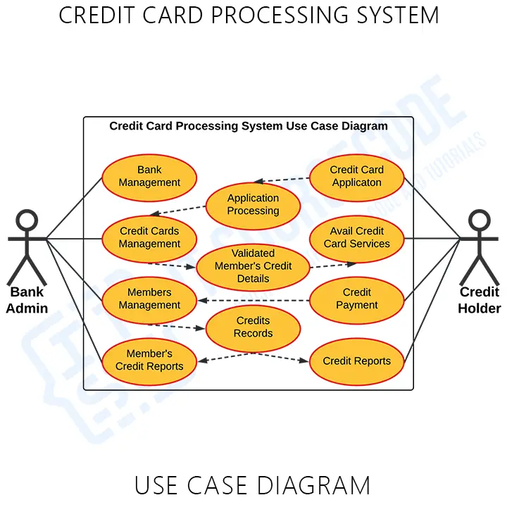
The Use Case Diagram for Credit Card Processing System with Explanation is discussed and clarified in this article. These use case diagrams are shown in different processes and are based on credit card processing. This diagram contains the main use cases and users in the system. These use cases are elaborated by either use case connected to them by the broken arrows.
The broken arrows are indications that the following diagrams connected to them are parts of a process. They could either be one of the indications which were the include or extend. The include indication means that the following use case should be performed to finish the task and the extend indication is otherwise.
The diagram shows the use cases in credit card processing. The processes mentioned can be modified and added with other ideas related to the credit card processing system. Your project use cases depend on the processes that your project requires.
You can add more to this and it is up to you how will you create your use case diagram. Only be precise with your information and consider the use cases that should be included.
Use Case Diagram for Credit Card Processing System Pdf
The Use Case Diagram for Credit Card Processing System PDF provides the information explaining the concepts of the project database. You may apply this information to your capstone project. You can also use it directly or modify its content depending on your project’s requirements.
Steps in Developing Use Case Diagram for Credit Card Processing System
Time needed: 5 minutes
Steps in creating a Use Case Diagram for Credit Card Processing System.
- Step 1: Familiarize Use Case Diagram Symbols
Use Case Diagram Symbols – are used to create a Use Case Diagram which was presented here. Their symbols and applications must be familiarized before you build the Use Case Diagram.
• Use Cases – Ovals with a horizontal shape symbolize the various uses that a user might have.
• Actors (Users) – Stick figures depict people that are using the use cases.
• Indicators (Association) – are used to know the connection of the system’s function or processes with another process. Its vital role is to figure out which actors are linked to and which use cases are in complex graphs.
• Container – is a box that limits the scope of a system to specific use situations. Situations, where the system is used outside of the box, would be deemed outside of the system’s scope. In the chainsaw example below, “Psycho Killer” is outside the scope of vocations.
Each of these use case diagram symbols shows the overall system structure. Emphasizing the System’s structure would be much easier by using these Use Case Diagram symbols. - Step 2: Determine the targeted users
After the symbol familiarization, you’ll need to determine your targeted users. Your targeted users will be the ones to use your project.
Your project is Credit Card Processing System for banks and lending companies. You may ask them about the common activities that they do when doing tasks in credit card processing. This information will help you in proceeding with the next step. - Step 3: Analyze the use cases included
Analyzation is very important in creating a use case diagram. It will help you understand the work of the diagram and avoid unwanted errors.
The gathered information from the targeted users is very useful in creating a use case diagram. You just need to evaluate these data and pick the general use cases.
From the general use cases, you will see the sub-cases that are included in them. But only include the useful processes and circumstances related to the credit card processing system. Then you’re ready for the next step. - Step 4: Plot the Use Case Diagram
To plot the use case diagram you will need the users, use cases, container (scope), and their indicators (association). You will base the flow of use cases on the evaluated information to have the exact Use Case Diagram.
To plot your diagram, you need to place first the users involved and the process they will perform.
Then place the figured use cases included in doing the process.
After that, you will trace the association of the use cases to know the series of interactions between the user/s and the system.
Finally, you put the container in the plotted diagram to separate the objects’ (users and system) scope. This is to identify what are the processes that are under them or should be performed.
Conclusion:
You need to know the methods used to design and develop the Credit Card Processing System. That is because you cannot perfectly create a fully-functional system without it. But if you create this diagram, you will know the possible inputs and scenarios that the system should process and perform. Not only that, you will find out the needed processes and connect them to the other UML Diagrams.
The activity diagram can be used to model the system’s use cases. These systems are also captured in the use case diagram, which describes the flow from one system to the next. By completing the Use Case Diagrams per module or process, you will easily achieve your desired system. Check out our Related and Recommended Articles for more Learnings and Information.
Related Articles:
- Use Case Diagram for Course Registration System
- Face Recognition Attendance System Use Case Diagram
- Use Case Diagram for E-Commerce Website
- Online Airline Reservation System Use Case Diagram
- Event Management System Use Case Diagram
Recommended Articles from the Author:
Inquiries
If you have inquiries or suggestions about Use Case Diagram for Credit Card Processing, just leave us your comments below. We would be glad to hear to concerns and suggestions and be part of your learning.
Keep us updated and Good day!