

The Class Diagram for School Management System is a designed structure that shows the classes and their relationships. This diagram is made to guide programmers along with the School management system development.
It contains the class attributes, methods as well as the relationships between classes. These mentioned contents makes sure that your School management system development must inline with what should be its functions.
Read the articles linked below to learn more about Diagrams.
- Class Diagram for Student Management System
- School Management System Project UML Diagrams
- Class Diagram for College Management System
- Component Diagram for School Management System
- Student Management System UML Diagrams
- School Management System Sequence Diagram
- Activity Diagram for School Management System
- Use Case Diagram for School Management System
Class Diagram for School Management System design considerations
The system can empower school leaders to lead their teachers and students through reforms that result in higher learning outcomes; bring resources, including funds, down to the control of schools to spur change in line with decentralization; and strengthen partnerships with communities to invest time, money, and resources in order to achieve higher learning outcomes.
How to create the School Management System UML Class Diagram?
Now to create the Diagram for School System, you will first determine the classes. So the classes that are included in School management would be the students, enrollment, instructors, subjects, courses, registrar and transaction.
The mentioned classes were just general. If you want a more complex or wider scope of your School management system, then you can add your desired classes. You must also include the database on your Class Diagram for your system.
Free tool
Generate this Class Diagram in 3 minutes
You have the structure. Now build it with your own entities. The School / Enrollment template comes pre-filled, so you rename what does not match your project and export straight into your Chapter 3.
Open the School / Enrollment template →3 free diagrams every week. No credit card needed.
Simple Class Diagram for School Management System
Here, I will be showing you the sample constructed diagram. It was provided with its attributes with matching methods.
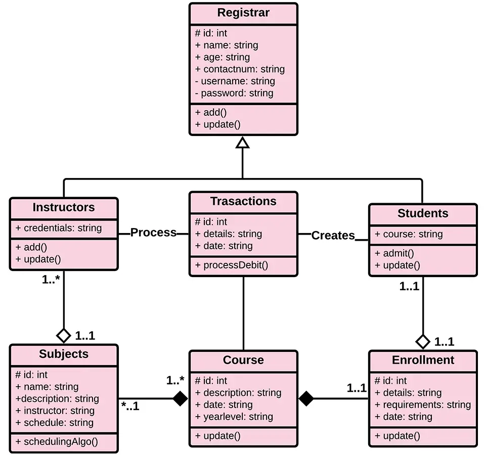
The illustration shown in this article gives you the hint on how will you design your own class Diagram. It has a simple idea of how the class Diagram works.
Bonus Tips on Designing the Class Diagram of School Management System
To design your Class diagram, you may use platforms and editing tools online. These tools are helpful since they already have the needed symbols to illustrate your class diagram.
You just have to plot the included classes, attributes and methods. Then you will put the appropriate relationships that the system requires.
The platforms or online tools that you may use are:
- Lucidchart
- Creately
- Smartdraw
- Edrawmax
- Canva
Conclusion
The School Management System Management System is a modeled diagram that explains its classes and relationships. The diagram depicts the names and attributes of the classes, as well as their links and, their methods.
It is the most essential type of UML diagram which is critical in software development. It is an approach to show the system’s structure in detail, including its properties and operations.
Inquiries
Now let me ask you something. What have you learned through the discussion? May this article help you with your projects in the future!
Keep us updated and Good day!
Working school management source code that implements this diagram
The diagram above defines the flows; these are the actual school management systems on itsourcecode.com that implement them. Pick one in your team’s stack and you have a working reference to point your panel at when they ask “show me where this flow actually runs in code.”

Java: School Management System in Java
Java Swing + JDBC + MySQL. Each UML class becomes a .java file; perfect for OOP defense.

Laravel (PHP): School Management in Laravel
Laravel + Eloquent. Eloquent models map one-to-one with classes in your UML.

CodeIgniter (PHP): School Management in CodeIgniter
CI4 + Bootstrap. MVC variant if your panel prefers framework code over vanilla PHP.
How to use this for your Chapter 3 (Methodology): download the project in your stack, then map each process and data store in this diagram to a specific module, controller, or table in the downloaded source. That mapping IS the bridge between your design chapter and your implementation chapter, the single thing panels want to see traced end to end.
How to read a class diagram
A class diagram has three components in each class box: name (top), attributes (middle), operations/methods (bottom). Relationships between classes are shown as lines with different symbols.
- Association. Plain line means two classes know about each other.
- Inheritance / Generalization. Line with a hollow arrowhead pointing to the parent class.
- Realization. Dashed line with hollow arrowhead pointing to an interface.
- Aggregation. Line with a hollow diamond at the “whole” end (e.g., Department has Employees).
- Composition. Filled diamond at the “whole” end (e.g., House is composed of Rooms).
- Dependency. Dashed arrow: one class uses another temporarily.
Cardinality notation
- 1. Exactly one
- 0..1. Zero or one (optional)
- 1..*. One or more (mandatory + many)
- 0..* or *. Zero or more (any number)
- 1..5. Between 1 and 5
Common capstone mistakes to avoid
- Missing cardinality. Every association must have numbers on both ends.
- Getters/setters listed as separate methods. Show only meaningful business methods; getters/setters are implied.
- Utility classes. Do not clutter the diagram with String, Date, etc.
- No visibility modifiers. Use + (public), – (private), # (protected) on attributes and methods.
- Confusing aggregation vs composition. Composition means the part cannot exist without the whole.
Where the class diagram fits in Chapter 3
- Section 3.2 (Object-Oriented Analysis and Design). The class diagram is usually placed here.
- Reference from the ER diagram. Show how database tables map to classes.
- Reference from the use case diagram. Each use case triggers operations on one or more classes.
- Include a legend. Explain the notation for panel members who may not remember UML conventions.
Official documentation
Working source code for this system
Download the actual implementation of this system in your preferred language. Each project includes source code, database, and setup instructions for BSIT capstone use.
- PHP: Car Driving School Management System in PHP with Source Code
- VB.NET: School Management System Version 3.0 in VB.net with Source Code
- Java: University Management System Project in Java With Source Code
- Python: College Management System Using Django with Source Code
- Django: College Management System Using Django with Source Code
- Laravel: School Management System in Laravel With Source Code
Frequently asked questions
What is a class diagram used for in BSIT capstone?
A class diagram shows the static structure of the system: classes, attributes, methods, and relationships (inheritance, association, aggregation, composition). It goes in Chapter 3 of the capstone documentation and communicates the object-oriented design of the system.
What tool should I use to draw the class diagram?
Free options: draw.io (browser-based, saves to Google Drive), Lucidchart free tier, PlantUML (text-based, version-controllable), StarUML (30-day trial then reduced feature set), Visual Paradigm Community Edition. Paid options: Microsoft Visio, Lucidchart pro, Enterprise Architect. For BSIT capstones, draw.io is the most commonly used free tool.
How detailed does the class diagram need to be for capstone defense?
Panel members expect the diagram to match the actual system implementation. Include every major class/use case/entity relevant to the system. Omit trivial helper classes. Every diagram element should have a clear justification. Aim for 1-2 diagrams that fully cover the system, not many partial ones.
Should I use black-and-white or colored diagrams?
Black-and-white is standard for capstone documentation to match the thesis format. Use color only if it improves clarity (e.g., grouping subsystems). Ensure text is readable at printed size (10pt minimum for labels).
Where does this diagram go in the capstone documentation?
Chapter 3 (System Design and Methodology) typically holds all UML diagrams. Introduce each diagram with a 1-paragraph description explaining what it shows and how to read it. Reference specific elements in the surrounding text so panel members can follow the design rationale.

Mary Grace G. Patulada
Programmer & Technical Writer at PIES IT Solution
Mary Grace G. Patulada (pen name ‘Nym’) is a programmer and writer at PIES IT Solution with a BSIT background from Carlos Hilado Memorial State College, Binalbagan Campus. Authored 370+ UML diagram tutorials and capstone documentation guides at itsourcecode.com. Specializes in UML (class, use case, activity, sequence, component, deployment), DFD, and ER diagrams for BSIT capstone projects.
Expertise: UML Diagrams · DFD · ER Diagrams · Use Case Diagrams · Activity Diagrams · Capstone Documentation · PHP
· View all posts by Mary Grace G. Patulada →
2026-2027 hybrid learning: what school management diagrams need to show
Philippine schools in 2026 run parallel face-to-face and online-hybrid tracks for most subjects, and capstone panels expect your school management system class diagram to reflect this reality. Additions worth including:
- class LearningMode with values FACE_TO_FACE, ASYNC_ONLINE, SYNCHRONOUS_ONLINE, HYBRID_ROTATION. Every Class instance should carry this attribute now because DepEd and CHED require reporting on modality mix.
- class LMS_Integration as a stub showing your school pulls attendance from Google Classroom, Moodle, or Canvas. Even if your capstone does not implement this, panels ask about it and appreciate seeing the integration point acknowledged.
- class AttendanceLog should support both physical (QR scan, biometric) and online (LMS-derived, time-tracked). Add a source enum: BIOMETRIC, QR_CODE, LMS_AUTOMATED, MANUAL.
- class ParentPortal with methods viewGrades(), viewAttendance(), acknowledgeReport(). Since 2024 PH parents expect real-time grade access via a portal. Not including this is a common panel critique.
These four class additions align a textbook school system with the actual mixed-modality environment PH panels are grading against in 2026-2027.