
UML activity diagram for hospital management system – is one of the UML diagrams built to give the proponents the right ideas on how to develop the said software. When designing the activity diagram, you must know the flow of activities done in doing hospital management.
Why is that? it is because this will help you, your readers and users about how should the software behave once it is in use. It’s activity diagram is illustrated with the use of symbols like actors, swimlanes and arrows to understand the Hospital Management System core.
The users of this Hospital Management System would be the patients, physicians or nurses and the hospital manager and they are essential in creating its UML activity diagram.
By determining the users of the system, it would be much easier for you to build the interactions and activities in the system.
Then you will be able to foresee the behavior of the system towards its user. So you should be aware that your system must be user-friendly and effective for its users.
What is a Hospital Management System UML Activity Diagram?
To have a clear understanding about it, let me tell you its purpose and role. The Hospital Management System must have an activity diagram so that the programmers would have a basis on how should the software approach its users.
It is because, the activity diagram guides the programmer in creating the software and its must-have behavior. So if you want a friendly and effective or easy-to-use software, then you must also complete the activity diagram.
Through the activity diagram, you’ll be able to illustrate the flow of activities and know what should be the interactions between the system and its users.
Your readers and users will also be guided about how would they use the system by looking into its activity diagram. So its best for you to explain your thoughts about the system through activity diagram.
Activity Diagram Symbols:
Now before we create the Activity diagram of Hospital Management System, you must know first the symbols used to make it. And here are the symbols used in Activity Diagram.
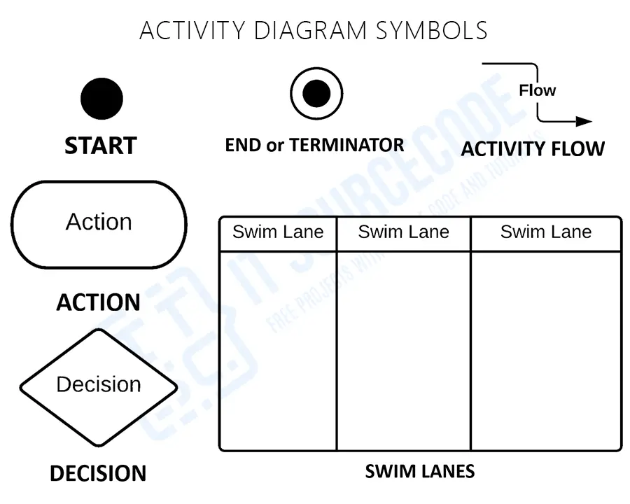
The activity diagram uses symbols just like swimlanes, actors and arrows to distinguish clearly the interaction between the users and the hospital management system.
This activity diagram uses swimlanes to know how does the system respond to the users whenever they make a transaction or a request on the hospital management system.
You must be familiar with these symbols in order for you to distinguish what should you put in the illustration to avoid misunderstandings.
This is also to educate you about the activity diagram symbols so you and the users would understand the system’s behavior.
In addition to that, being familiar with these activity diagram symbols will help you show the detailed parts and interactions that should happen when you develop the System.
Then this thought enables you to have right ideas on how you would develop the system that you want.
Additional Knowledge
The activity diagram works perfectly with the other UML Diagrams which were available also on our site. They are the Hospital Management System Use Case Diagram, Data Flow Diagram, Entity Relationship Diagram and many more.
These diagrams served as the blueprint designs to foresee the needed functions of a working Hospital Management System.
Activity Diagram of Hospital Management System
Time needed: 5 minutes
Here’s the UML activity diagram designs of Hospital Management System that you can use for your own Final year Project. Note that you may change the ideas given in this activity diagram to meet the scope or expectation on hospital management system project that you desired. The given ideas here are sorted based on the system users to give you more detailed examples.
- Hospital Management System Activity Diagram for the Patient Users

Since it is obvious in every hospital management system to have patients to be the user of it. And the designed activity diagram here shows the interaction between the software and the patient.So, as you can see, the diagram has its flow of activities that is based in doing transactions in a hospital. This flow of activities must be present in your software to justify the reason why you pursue your project.
- Hospital Management System Activity Diagram for the Admin Users
Another scenario in doing hospital management system for admin is presented in this UML activity diagram. You can see here the interaction of the system and the hospital admin. Since the hospital admin is in charge of monitoring every transactions in the hospital and checking of the appointments made by the patient. So the situation here shows that the system helps in doing these task with ease. An it is better if you set the flow of activities through the diagram before developing the software. - Hospital Management System Activity Diagram Scenario for the Two Users
Now, here’s a design UML activity diagram design for two users in hospital management system. It was made to give you a sample situation when there are two users are involve in a certain activity. For example, when discharging a patient, the admission bill and treatment must be monitored. So it is a must that you design first the core flow of the software before developing it.


You should be informed that these diagrams can be modified to achieve your desired system behavior. You can also create your unique system function to justify all of your clients needs. And if you want, you can copy all the ideas presented here so you won’t need to create a new one.
Official documentation
Working source code for this system
Download the actual implementation of this system in your preferred language. Each project includes source code, database, and setup instructions for BSIT capstone use.
- PHP: Hospital Management System Project In PHP With Source Code
- VB.NET: Hospital Management System Database Design
- Java: Project On Hospital Management System In Java Source Code
- Python: Django Online Medical Management System with Source Code
- Django: Django Online Medical Management System with Source Code
- Laravel: Clinic Management System Project in Laravel with Source Code
Frequently Asked Questions
What is an Activity Diagram for Hospital Management System?
An Activity Diagram for Hospital Management System is a UML behavioral diagram that visualizes patient workflow , from registration, appointment booking, consultation, diagnosis, treatment, billing, to discharge. It shows the sequence of activities, decision points (admit or discharge), parallel processes (lab tests, prescription), and actor responsibilities (Patient, Doctor, Nurse, Admin).
What are the main workflows in Hospital Management Activity Diagram?
Main workflows in Hospital Management Activity Diagram include: Patient Registration → Appointment Booking → Doctor Consultation → Diagnosis → Treatment Plan → Lab Tests (parallel) → Prescription → Billing → Payment → Discharge or Admission. Emergency cases have separate workflow with priority handling and immediate care.
What actors are shown in Hospital Activity Diagram swim lanes?
Hospital Management Activity Diagram swim lanes typically include: Patient (registers, books appointments, makes payments), Receptionist (manages registration and appointments), Doctor (consults, diagnoses, prescribes), Nurse (records vitals, assists), Lab Technician (conducts tests), Pharmacist (dispenses medication), and Admin/Billing (handles billing and reports).
How is patient admission shown in Hospital Activity Diagram?
Patient admission in Hospital Activity Diagram is shown as: after consultation, a decision diamond ‘Requires Admission?’. If Yes , flow goes to Bed Assignment → Ward Allocation → Treatment Plan → Continuous Care activities. If No , flow goes to Prescription → Billing → Discharge. The diagram clearly shows different paths based on patient condition.
Can this Activity Diagram be used for capstone documentation?
Yes, the Hospital Management System Activity Diagram is excellent for capstone documentation. It demonstrates complex real-world workflow modeling, includes multiple actors with swim lanes, handles conditional flows (admission vs. discharge), and pairs well with other diagrams like Use Case, Class Diagram, and ER Diagram for complete IT capstone or thesis documentation.
Conclusion
It is essential for you to know the activity diagram design before developing the Hospital Management System and make it more understandable using swimlanes.
That is because you cannot perfectly create a fully-functional system without it. But if you create this activity diagram, you will know the possible inputs and scenarios that the system should process and perform.
Not only that, you will find out the needed processes and synchronize them to the other UML Diagrams. By completing the Activity Diagrams per module or per processes, you will easily achieve your desired system.
But you don’t have to think harder because we are continuously creating UML diagram for all possible system and software that you can use. So keep on visiting our site so you would be updated about our new discussion and diagrams.
Related Articles:
- Hospital Management System Project UML Diagrams
- Hospital Management System Class Diagram | UML
- DFD Diagram for Hospital Management System
- Component Diagram for Hospital Management System
- HOSPITAL MANAGEMENT SYSTEM PROJECT DOCUMENTATION
- Hospital Management System Sequence Diagram | UML
Inquiries:
Now, what have you learned through our discussion? Have you determine the Diagrams that you must create? What project do you have in mind?
And if you have ideas or concerns with our discussion, do not hesitate to leave us your suggestions and questions. Those are highly appreciated. Thank you so much and have a good day!
Check out our Related and Recommended Articles for more Learnings and Information.

Mary Grace G. Patulada
Programmer & Technical Writer at PIES IT Solution
Mary Grace G. Patulada (pen name ‘Nym’) is a programmer and writer at PIES IT Solution with a BSIT background from Carlos Hilado Memorial State College, Binalbagan Campus. Authored 370+ UML diagram tutorials and capstone documentation guides at itsourcecode.com. Specializes in UML (class, use case, activity, sequence, component, deployment), DFD, and ER diagrams for BSIT capstone projects.
Expertise: UML Diagrams · DFD · ER Diagrams · Use Case Diagrams · Activity Diagrams · Capstone Documentation · PHP
· View all posts by Mary Grace G. Patulada →