In this article, I will show you how to interface a sound sensor module in Arduino.
Using this module, you can capture sound as input to control other parts of your device.
Integrating this into your projects can greatly improve the functionality of your device.
Sound Module Interfacing in Arduino: Steps in Creating the Device
Here are the steps in interfacing the sound module in Arduino.
- Gathering the Components
The first thing to do is to collect the hardware components for the Arduino device.
Arduino Uno
Sound Sensor Module - Connecting the Components
Connect the components to the Arduino Uno. Please refer to the wiring diagram below.
- Coding the Arduino
Third step is about coding the Arduino device.
- Upload the Sketch
Final step is uploading the sketch to the Arduino.
Sound Module Interfacing in Arduino: Detailed Explanation
Step 1: Gathering the Components
To start off, this project will have two parts: the Arduino Device and the Program. First thing to do is to collect the hardware components and make the device. To do that, you will be needing the following:
| Quantity | Components |
| 1 | Arduino Uno |
| 1 | Sound sensor module |
Arduino UNO
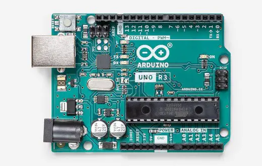
You will be using Arduino Uno for this project. It is an easy to use microprocessor board. Arduino Uno is suitable for any projects and is the cheapest and widely used microprocessor board in the Arduino family. This is great for all kinds of IoT projects.
Sound Sensor Module
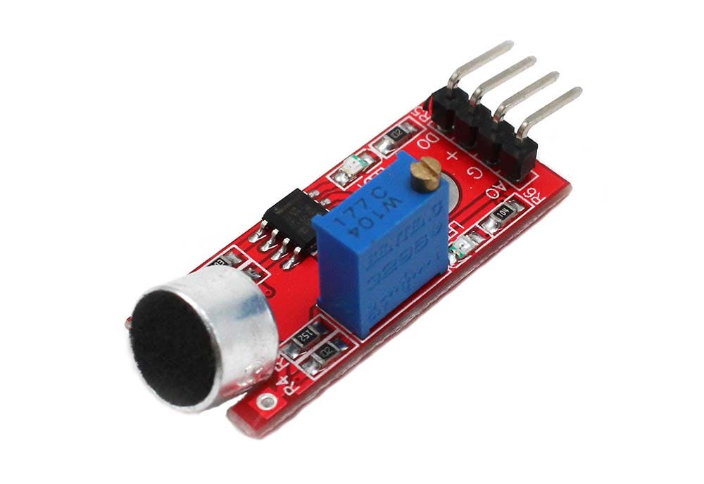
This is a sound sensor module you will be using. It has 4 pins – GND, 5V, and two output pins for Digital and Analog signals. It has two built-in LEDS – one Power indicator and the other blinks when sound is detected. You can also adjust its sensitivity by tuning the knob clockwise.
Take note that some modules will have 3 pins but it is still the same. It is just that other modules do not provide two output pins.
Step 2: Connecting the Arduino Components
Now you are ready to connect the components to the Arduino Uno. Connect the power and the ground pins to 5V and GND. Next is to connect the VRX and VRY to A0 and A1. Lastly, connect SW pin to a digital pin.
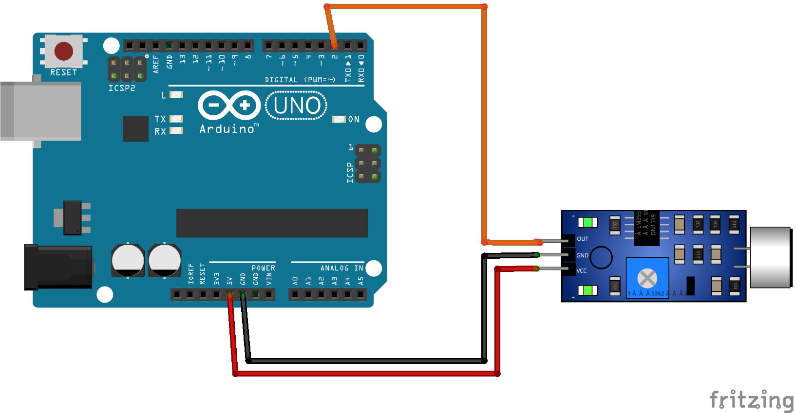
In the diagram, the sound sensor module is connected to 5V pin of the Arduino. For the output pin, connect it to digital pin 2. if you have the 4-pin variant, use the digital pin of the module.
Step 3: The Arduino Code
Copy the code below to a new sketch in the Arduino IDE. Once done, you can upload it to the Arduino Uno.
#define sensorPin 2

// Variable to store the time when last event happened
unsigned long lastEvent = 0;

void setup() {
  pinMode(sensorPin, INPUT);  // Set sensor pin as an INPUT
  Serial.begin(9600);
}

void loop() {
  // Read Sound sensor
  int sensorData = digitalRead(sensorPin);

  // If pin goes LOW, sound is detected
  if (sensorData == LOW) {

    // If 25ms have passed since last LOW state, it means that
    // the clap is detected and not due to any spurious sounds
    if (millis() - lastEvent > 25) {
      Serial.println("Clap detected!");
    }

    // Remember when last event happened
    lastEvent = millis();
  }
}
Now upload the sketch to the Arduino.
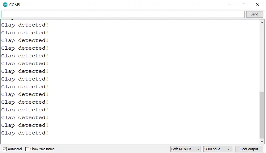
Step 4: Upload the sketch
After you successfully upload the sketch, open the serial monitor of the Arduino. Here you can see that the module detects a clapping sound.
Conclusion
So there you have it! Sound Sensor Module Interfacing in Arduino. This project is intimidating at first but you will see that it is fairly easy to do. You can combine this to other Arduino projects and build an awesome system!
Download
Click the button below to download the sketch for the Sound Sensor.
Related Articles
Inquiries
Feel free to write your questions about this at the comments below.