
Law Firm Management System Thesis Chapter 3
This Law Firm Management System Thesis Chapter 3 is all about the step-by-step method on how the proponents will design and develop the proposed study.
SYSTEM DEVELOPMENT LIFE CYCLE (SDLC) or the Software Development Life Cycle is a process that produces software with the highest quality and lowest cost in the shortest time.
SDLC includes a detailed plan for how to develop, alter, maintain, and replace a software system. It involves several distinct stages, including planning, design, building, testing, and development.
In short, SDLC works by lowering the cost of software development while simultaneously improving quality and shortening production time. In this study, the proponents will use the RAD or the Rapid Application Development Methodology as a guide for processing the proponents’ system flow.
RAPID APPLICATION DEVELOPMENT METHODOLOGY

Figure 1: Rapid Application Development Methodology
Figure 1: Shows the RAD or Rapid Application Development Diagram that is used by the proponents as their guide for the system. It shows the step-by-step process of the proponents and the research on how the system will be implemented and done from the beginning process until the end.
Rapid Application Development is easier to use than other methodology, specifically compared to the waterfall method which is not that effective; the diagram shows the step-by-step process so that the proponents can make sure that the system that they are proposing will be effective and the problems that might encounter can be redo by reviewing every step.
In RAD, the proponents can make multiple iterations and updates rapidly without starting again from scratch every time the proponents wanted to change something.
The advantage of RAD model from the other methodologies is the efficiency in consuming the time of the proponents in implementing the system.
Analysis and Quick Design of Law Firm Management System Thesis
In this phase, the proponents analyzed the information and data that they gathered so that the proponents can foresee what design they will make that will suit for the process for the proponents study.
Demonstrate
The information and data that the proponents gathered will be their guide in creating an efficient and effective interface. With the help of development tools and guides, the proponents’ system can now start to create its structure and functions.
Refine
The proponents will use the guides to know if there is an error in the proposed system so that they will be able to change and correct the errors that the system might encounter.
Build
The proponents will tackle the process on how to use the proposed system in order for the users to easily and efficiently manage and manipulate the proposed system.
Testing and Implementation
The proponents will make sure that the proposed system is functioning well, easy to use and easy to understand. The proponents must do the testing to be able to know the requirements that is still needed for the proposed system and to be able to redo it.
The proponents must conduct a system testing to the administration of law firms and ask more suggestions if there’s still something to be change or add. The proposed system is only implemented to the Law Firm.
Case Study: Law Firm Management System
For this mini case, the task is to make a design for a system that can be used to manage transactions and etc. The name of the proposed system is Law Firm Management System.
The system provides efficient managing in terms of transactions. The Law Firm Administrator itself manages all of the transactions the system have.
Lawyers in the organization are the one who assigned schedule and availability to each client. The transaction of each client are managed by a Lawyer if what the cases are and where, and defining the cases schedule.
The Lawyers organization or the Law Firm aims to use the Law Firm Management System to get a better control and visibility to the transaction management and to also streamline the process of generating and managing schedules for different cases.
Law Firm Management System with SMS Notification Use Case Model
Figure 2: Law Firm Management System with SMS Notification Use Case Diagram
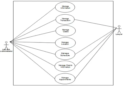
Figure 2: This figure shows the generalization of use cases of the proposed system
Manage Lawyer’s Information
Figure 3: Manage Lawyer’s Information Use Case Diagram
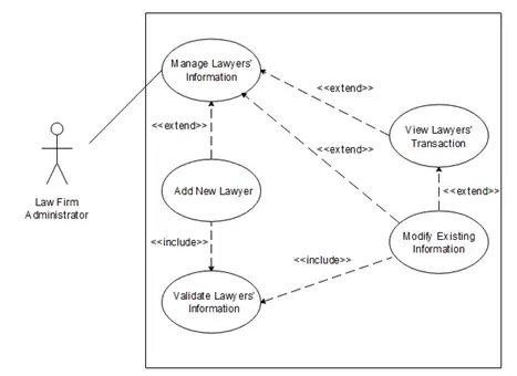
Figure 3: This figure shows the breakdown processes of the manage lawyer use
Table 2. Manage Lawyers Information
| Use Case Name: | Manage Lawyer’s Information | |
| Actors: | Law Firm Administrator | |
| Description: | This use case describes how the Law Firm Administrator manages the Lawyer’s information by adding new Lawyer and modifying existing ones. | |
| Pre-conditions: | Law Firm Administrator is logged into Law Firm Management System | |
| Post-conditions: | Law Firm Administrator has received an acknowledgement from the system successful or not completed | |
| Normal Flow: | Actor | System |
| Law Firm Administrator selects Add New Lawyer Law Firm Administrator inputs and submit lawyers information Law Firm Administrator selects Modify Existing Information Law Firm Administrator inputs new Lawyers information Law Firm Administrator has received an acknowledgement from the system that the lawyers info has been modified, or if not, a message explaining the failure Law Firm Administrator view Lawyers transaction | System invokes Create Add New Lawyer and display form 2.1 System validates Lawyers information 2.2 System will display the new lawyer’s info into the Lawyer’s info table System invokes Modify Existing Lawyer System validates lawyer’s information 6.1 System will display the transaction of the lawyer | |
| Alternative Flows: | Lawyers information validation failed, display an error message, and go to step 2Lawyers modification validation failed, display an error message, and go to step 4 | |
| Business Rules: | Lawyer’s information validation script/code conditions |
Table 2: Shows the flow of managing the Lawyers Information.
Manage Transaction
Figure 4: Manage Transaction Use Case Diagram
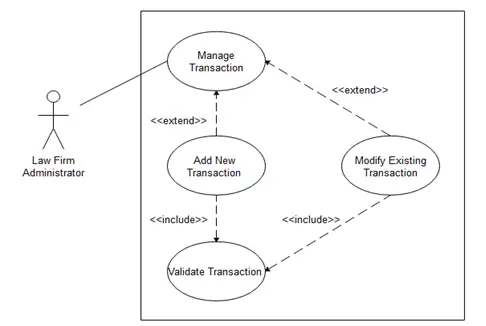
Figure 4: This figure shows the breakdown processes of the manage transaction use case
Table 3. Manage Transaction
| Use Case Name: | Manage Transaction | |
| Actors: | Law Firm Administrator | |
| Description: | This use case describes how the Law Firm Administrator manages all of the transactions by creating new transactions and modifying existing ones. | |
| Pre-conditions: | Law Firm Administrator is logged into Law Firm Management System | |
| Post-conditions: | Law Firm Administrator has received an acknowledgement from the system successful or not completed | |
| Normal Flow: | Actor | System |
| Law Firm Administrator selects Add New Transaction Law Firm Administrator input and submit transaction Law Firm Administrator selects Modify Existing Transaction Law Firm Administrator inputs new transaction Law Firm Administrator has received an acknowledgement from the system that the transaction has been modified, or if not, a message explaining the failure | System invokes Add New Transaction and display form 2.1. System validates transaction 2.2. System will display the new transaction into the Lawyer’s info table 3.1. System invokes Modify Existing Transaction 4.1. System validates transaction | |
| Alternative Flows: | 2.1. Transactions’ validation failed, display an error message, and go to step 2 4.1. Transactions’ modification validation failed, display an error message, and go to step 4 | |
| Business Rules: | Transactions’ validation script/code conditions |
Table 3: Shows the flow of managing the Transactions
Manage Cases Information
Figure 5: Manage Cases Use Case Diagram
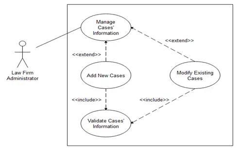
Figure 5: This figure shows the breakdown processes of the manage cases use case
Table 4. Manage Cases
| Use Case Name: | Manage Cases | |
| Actors: | Law Firm Administrator | |
| Description: | This use case describes how the Law Firm Administrator manages all of the cases by creating new cases and modifying existing ones. | |
| Pre-conditions: | Law Firm Administrator is logged into Law Firm Management System | |
| Post-conditions: | Law Firm Administrator has received an acknowledgement from the system successful or not completed | |
| Normal Flow: | Actor | System |
| Law Firm Administrator selects Add New Case Law Firm Administrator input and submit the new cases’ information Law Firm Administrator selects Modify Existing Cases Law Firm Administrator inputs new case Law Firm Administrator has received an acknowledgement from the system that the new case has been modified, or if not, a message explaining the failure | System invokes Add New Case and display form 2.1. System validates case 2.2. System will display the new case into the Cases’ info table 3.1. System invokes Modify Existing Cases 4.1. System validates cases | |
| Alternative Flows: | 2.1. Cases’ information validation failed, display an error message, and go to step 2 4.1. Cases’ modification validation failed, display an error message, and go to step 4 | |
| Business Rules: | Cases’ information validation script/code conditions |
Table 4: Shows the flow of managing the Cases.
Manage Location’s Information
Figure 6: Manage Locations’ Information Use Case Diagram
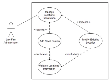
Figure 6: This figure shows the breakdown processes of the manage locations use case
Table 5. Manage Locations
| Use Case Name: | Manage Locations | |
| Actors: | Law Firm Administrator | |
| Description: | This use case describes how the Law Firm Administrator manages all of the locations by creating new locations and modifying existing ones. | |
| Pre-conditions: | Law Firm Administrator is logged into Law Firm Management System | |
| Post-conditions: | Law Firm Administrator has received an acknowledgement from the system successful or not completed | |
| Normal Flow: | Actor | System |
| Law Firm Administrator selects Add New Location Law Firm Administrator input and submit the new locations’ information Law Firm Administrator selects Modify Existing Locations Law Firm Administrator inputs new location Law Firm Administrator has received an acknowledgement from the system that the new case has been modified, or if not, a message explaining the failure | System invokes Add New Location and display form 2.1. System validates location 2.2. System will display the new location into the Locations’ info table 3.1. System invokes Modify Existing Location 4.1. System validates location | |
| Alternative Flows: | 2.1. Locations’ information validation failed, display an error message, and go to step 2 4.1. Locations’ modification validation failed, display an error message, and go to step 4 | |
| Business Rules: | Locations’ information validation script/code conditions |
Table 5: Shows the flow of managing the Locations
Manage Schedule
Figure 7: Manage Schedule Use Case Diagram
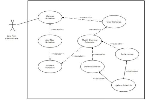
Figure 7: This figure shows the breakdown processes of the manage schedule use case
Table 6. Manage Schedule
| Use Case Name: | Manage Schedule | |
| Actors: | Law Firm Administrator | |
| Description: | This use case describes how the Law Firm Administrator manages the schedule of the lawyers by scheduling transactions and modifying existing schedules. | |
| Pre-conditions: | Law Firm Administrator is logged into Law Firm Management System | |
| Post-conditions: | Law Firm Administrator has received an acknowledgement from the system successful or not completed | |
| Normal Flow: | Actor | System |
| Law Firm Administrator selects Add New Schedule Law Firm Administrator input and submit new Schedule Law Firm Administrator selects view Schedule Law Firm Administrator selects Modify Existing Information Law Firm Administrator has received an acknowledgement from the system that the new schedule has been modified, or if not, a message explaining the failure Law Administrator selects Delete Schedule | 1.1. System invokes Add New Schedule and display form 2.1. System validates schedule 2.2. System will display the new schedule into the schedule’s info table 3.1. System will display the schedule’s information 4.1. System invokes Modify Existing Schedule 6.1. System invokes Delete Schedule | |
| Alternative Flows: | 2.2. Conflict in schedule, go to step 2 4.1. Conflict in schedule, go to step 4 6.1. Deletion of scheduled course failed, display an error message that explains why the process failed, and go to step 6 | |
| Business Rules: | 2.2. Algorithm/Script that checks conflict schedules in transactions |
Table 6: Shows the flow of managing the Schedule.
Manage Client’s Information
Figure 8: Manage Client’s Information Use Case Diagram
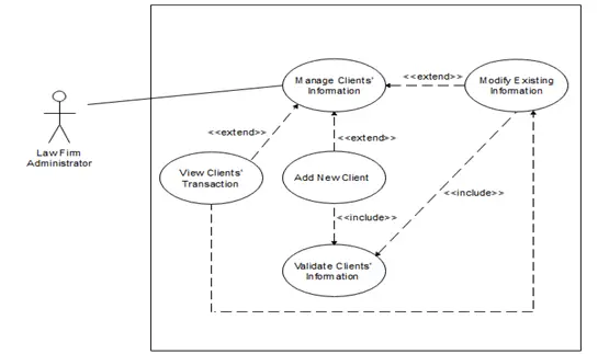
Figure 8: This figure shows the breakdown processes of the manage clients use case
Table 7. Manage Clients Information
| Use Case Name: | Manage Client’s Information | |
| Actors: | Law Firm Administrator | |
| Description: | This use case describes how a Law Firm Administrator manages the client’s information by modifying existing ones | |
| Pre-conditions: | Law Firm Administrator is logged into Law Firm Management System | |
| Post-conditions: | Law Firm Administrator has received an acknowledgement from the system successful or not completed | |
| Normal Flow: | Actor | System |
| Law Firm Administrator selects Add New Client Law Firm Administrator input and submit client’s information Law Firm Administrator selects Modify Existing Information Law Firm Administrator inputs new Clients information Law Firm Administrator has received an acknowledgement from the system that the clients info has been modified, or if not, a message explaining the failure Law Firm Administrator view clients transaction | 1.1. System invokes Add New Client and display form 2.1. System validates Client’s information 2.2 System will display the new client’s info into the Client’s info table 3.1 System invokes Modify Existing Client System validates client’s information 6.1 System will display the transaction of the client | |
| Alternative Flows: | Clients information validation failed, display an error message, and go to step 2 4.1 Clients modification validation failed, display an error message, and go to step 4 | |
| Business Rules: | 2.1. Clients information validation script/code conditions |
Table 7: Shows the flow of managing the Clients Information
Manage Appointments
Figure 9: Manage Appointment’s Use Case Diagram
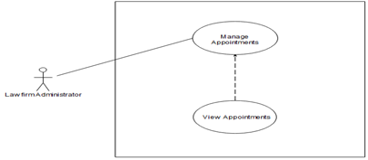
Figure 9: This figure shows the breakdown processes of the manage appointments use case
Table 8. Manage Appointment
| Use Case Name: | Manage Appointment | |
| Actors: | Law Firm Administrator | |
| Description: | This use case describes how the Law Firm Administrator manages the appointments of the clients by viewing it | |
| Pre-conditions: | Law Firm Administrator is logged into Law Firm Management System | |
| Post-conditions: | Law Firm Administrator has received an acknowledgement from the system successful or not completed | |
| Normal Flow: | Actor | System |
| Law Firm Administrator selects view Appointment | 1.1. System will display the Appointment’s information | |
| Alternative Flows: | 1.1. Failed viewing appointment, display an error code, go to step 1 | |
| Business Rules: | 1.1. Cases’ information validation script/code conditions |
Table 8: Shows the flow of managing the Appointment.
ACTIVITY DIAGRAM
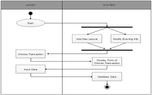
Figure 10: Lawyers Information Activity Diagram
Figure 10: Shows the activities done in managing the lawyers’ information
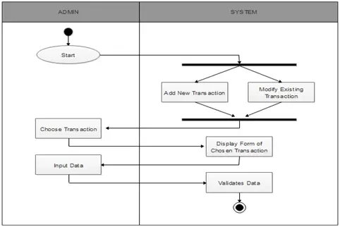
Figure 11: Transactions’ Activity Diagram
Figure 11: Shows the Activities happens in managing transaction
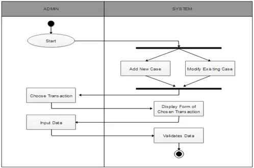
Figure 12: Case Information Activity Diagram
Figure 12: Shows the activities happens in managing the case information.
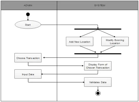
Figure 13: Locations Information Activity Diagram
Figure 13: Shows the activities happens in managing the locations information.
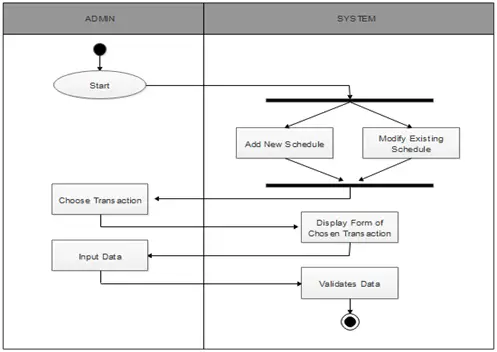
Figure 14: Schedule Activity Diagram
Figure 14: Shows the activities happens in managing the schedules.
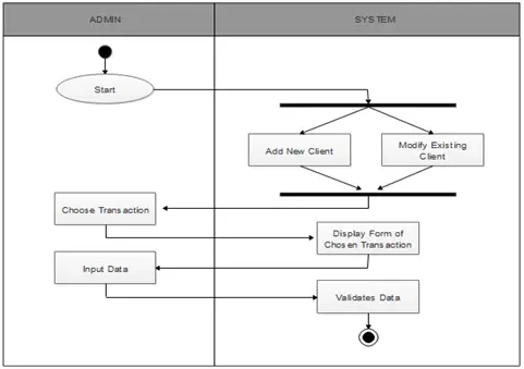
Figure 15: Clients’ Information Activity Diagram
Figure 15: Shows the activities happens in managing clients’ information.
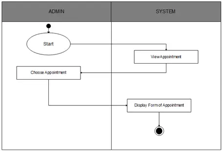
Figure 16: Appointments’ Activity Diagram
Figure 16: Shows the activities happens in managing appointments.
CONTEXT DIAGRAM
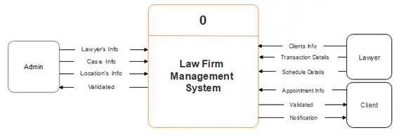
Figure 17: Context Diagram
Figure 17: Shows the main actors and main process of the Law Firm Management System and its flow of data.
DATA FLOW DIAGRAM
Figure 18: Law Firm Management System Data Flow Diagram Level 0
Figure 18: Shows the breakdown processes of the context diagram of the system.
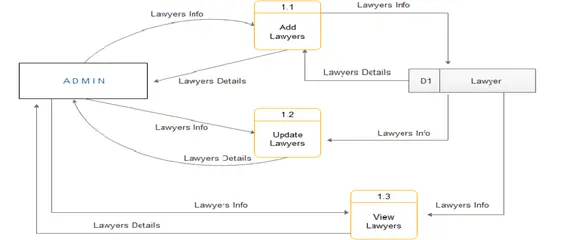
Figure 19: Lawyer’s Information Level 1 Data Flow Diagram
Figure 19: Shows the breakdown processes of the level 0 Lawyer’s information.
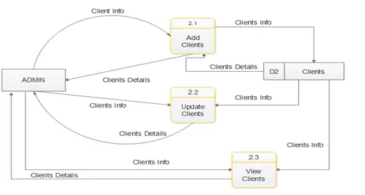
Figure 20: Client’s Information Level 1 Data Flow Diagram
Figure 20: Shows the breakdown processes of the Client’s Information.
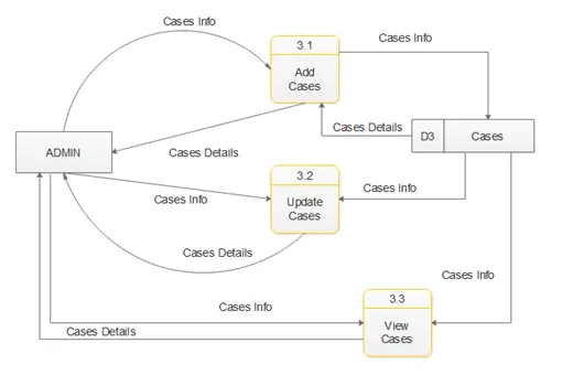
Figure 21: Cases’ Information Level 1 Data Flow Diagram
Figure 21: Shows the breakdown processes in managing Cases’ Information.
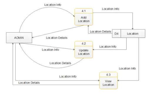
Figure 22: Location’s Information Level 1 Data Flow Diagram
Figure 22: Shows the breakdown processes in managing Locations’ Information
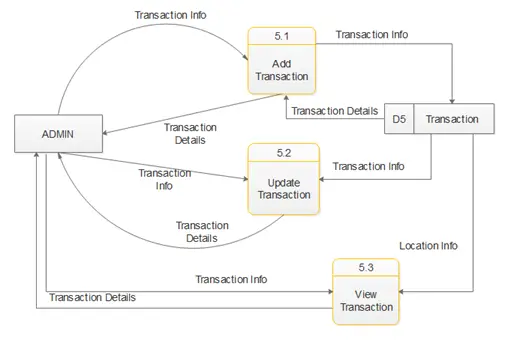
Figure 23: Transactions Information Level 1 Data Flow Diagram
Figure 23: Shows the breakdown processes in managing transactions.
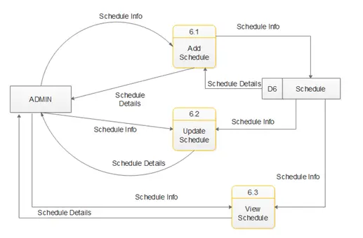
Figure 24: Schedules Information Level 1 Data Flow Diagram
Figure 24: Shows the breakdown processes in managing schedules.
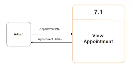
Figure 25: Appointments Level 1 Data Flow Diagram
Figure 25: Shows the breakdown processes in managing appointments.
Entity Relationship Diagram of Law Firm Management System w/ SMS Alert
Data Dictionaries
These tables below provide the entire database tables details such as Field Name, Description, Type and Length.
Table 9. Lawyers
| Field Name | Description | Type | Length |
| Lawyer ID | Lawyers ID number | Int | 50 |
| First Name | First Name of Lawyer | Varchar | 225 |
| Last Name | Last Name of Lawyer | Varchar | 225 |
| Age | Age of Lawyer | Varchar | 225 |
| Gender | Gender of Lawyer | Varchar | 225 |
| Province | Lawyers’ Province | Varchar | 225 |
| City/Municipality | Lawyers’ Address | Varchar | 225 |
| Email Address | Lawyers’ Email Add | Varchar | 225 |
| Type | Type of Lawyer | Varchar | 225 |
| Contact No | Contact Number of Lawyer | Varchar | 225 |
Table 9: This shows the description, type and length of fields in Lawyers Table.
Table 10. Transaction
| Field Name | Description | Type | Length |
| Trans ID | Transactions ID number | Int | 50 |
| Case ID | Cases ID number | Int | 50 |
| Date & Time | Date & Time of transaction | Varchar | 225 |
| Lawyer ID | Lawyers ID number | Int | 50 |
| Client ID | Clients ID number | Int | 50 |
Table 10: This shows the description, type and length of fields in Transactions Table.
Table 11. Cases
| Field Name | Description | Type | Length |
| Case ID | Cases’ ID number | Int | 50 |
| Case Name | Name of Cases | Varchar | 225 |
| Description | Description of Cases | Text |
Table 11: This shows the description, type and length of fields in Cases Table.
Table 12. Location
| Field Name | Description | Type | Length |
| Location ID | Locations’ ID number | Int | 50 |
| Location | Name of Location | Varchar | 225 |
Table 12: This shows the description, type and length of fields in Locations Table.
Table 13. Schedule
| Field Name | Description | Type | Length |
| Sched ID | Schedules ID number | Int | 50 |
| Date & Time | Date & Time of Schedule | Varchar | 225 |
| Location ID | Locations’ ID number | Int | 50 |
| Trans ID | Transactions’ ID number | Int | 50 |
Table 13: This shows the description, type and length of fields in Schedules Table.
Table 14. Clients
| Field Name | Description | Type | Length |
| Client ID | Clients’ ID number | Int | 50 |
| First Name | First Name of Client | Varchar | 225 |
| Last Name | Last Name of Client | Varchar | 225 |
| Province | Clients’ Province | Varchar | 225 |
| City/Municipality | Clients’ Address | Varchar | 225 |
| Age | Age of Client | Varchar | 225 |
| Gender | Gender of Client | Varchar | 225 |
| Status | Status of Client | Varchar | 225 |
| Contact No | Contact Number of Client | Varchar | 225 |
| Citizenship | Citizenship of Client | Varchar | 225 |
Table 14: This shows the description, type and length of fields in Clients Table.
Table 15. Appointments
| Field Name | Description | Type | Length |
| Client ID | Clients’ ID number | Int | 50 |
Table 15: This shows the description, type and length of fields in Appointment Table.
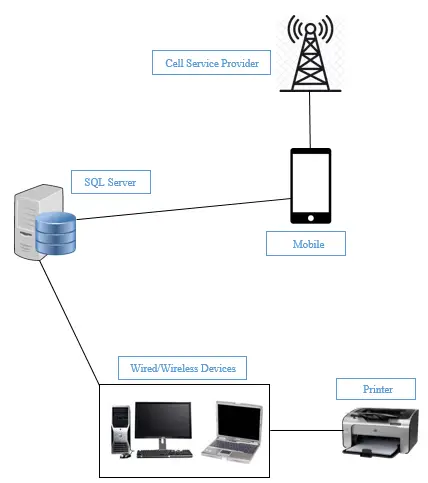
Architectural Framework of Law Firm Management System with SMS Alert
System Requirements
- Windows XP or later
- CPU with SSE2 support, including Intel Premium M, Core or Atom, AMD Athlon 64 or later
- 1 GB or more Computer RAM
- 1024×768 Screen Resolution
Hardware Specification:
The proponents’ used laptops Windows XP or later, a CPU with SSE2 support, including Intel Premium M, Core or Atom, AMD Athlon 64 or later 1 GB or more Computer RAM 1024×768 Screen Resolution
Software used for System Development:
- Microsoft Visual Studio 2008
- XAMPP
- PHPMyAdmin
Related Capstone Resources
- Classroom Management System Thesis Documentation Chapter 4
- Classroom Management System Thesis Documentation Chapter 5
- Classroom Management System Thesis Documentation Chapter 1
- Classroom Management System Thesis Documentation Chapter 2
- Online Supply And Inventory System Thesis Documentation Chapter 1
- Crane Thesis Chapter 5
Inquiries
If you have any questions or suggestions about Law Firm Documentation Methodology, please let me know by dropping your comment below.
Official references
Frequently asked questions
How many pages should a BSIT capstone chapter be?
Chapter 1 (Introduction) is typically 8-12 pages. Chapter 2 (RRL) is 15-25 pages. Chapter 3 (Methodology and System Design) is 15-30 pages depending on diagram count. Chapter 4 (Results) is 10-20 pages. Chapter 5 (Conclusions) is 5-10 pages. Total: 60-100 pages for the whole capstone.
What order should I write the chapters in?
Recommended order: Chapter 3 first (system design and methodology — most concrete), then Chapter 1 (introduction with the problem statement), then Chapter 2 (RRL to justify Chapter 1), then Chapter 4 (results — after implementation), then Chapter 5 (conclusions). This avoids rewrites and speeds up defense readiness.
What formatting style should I use for the capstone documentation?
Most Philippine BSIT programs require IEEE or APA 7th edition. Confirm with your adviser first. Use Times New Roman 12pt, double-spaced, 1-inch margins, and page numbers. Reference all sources properly and use consistent citation style throughout.
How many references do I need per chapter?
Chapter 1: 5-10 references. Chapter 2 (RRL): 20-40 references. Chapter 3: 10-15 references. Chapter 4-5: minimal, mostly self-referential. Recent sources (last 5 years) are strongly preferred over older ones.
What tools help write the capstone chapters?
Zotero or Mendeley for reference management, Grammarly for language check, Turnitin for plagiarism scan, Google Docs for collaboration with adviser, LaTeX (Overleaf) for advanced formatting, and ChatGPT or Claude for outline scaffolding (not for writing the actual content).

Adrian Mercurio
Full-Stack Developer at PIES IT Solution
Specializes in building complete capstone projects with full documentation. Strong background in PHP/MySQL development and database design. Has personally built and tested over 30 capstone-ready projects with ER diagrams, DFDs, and chapter-by-chapter thesis documentation.
Expertise: PHP, Laravel, Database Design, Capstone Projects, C#, C, C++, Python, AI Projects · View all posts by Adrian Mercurio →