
Online food ordering systems and websites are very dominant these days. To emphasize how it works, a DFD for the food ordering system is applied.
The DFD (Data Flow Diagram) represents the system’s flow of data and transformations. This transformation occurs when data enters and exits a system.
DFD represents and describes the food ordering system as a whole, including input, processing, and output.
The DFD diagram of the food ordering system consists of the following diagrams:
- Context Diagram (Level 0)
- DFD Level 1
- DFD Level 2
Let us know first the system’s inputs and outputs, processing, and databases.
| Input | Output | Processing | Databases |
| Customers’ Information | Order Confirmation | Manage Customer Information | Customer Database |
| Customer Order Details | Payment and Delivery | Manage Orders and Reservations | Orders Database |
| Sellers’ Permits (Information) | Transaction Reports | Schedule Deliveries | Product Database |
| Product’s Information | Revenue and Expenses | Manage Transactions and Payment | Payment Database |
Level 0 DFD of Food Ordering System
A context diagram (level 0 data-flow diagram) defines the boundaries of the food ordering processes. It demonstrates how data flows between the system and external entities.
Through the DFD level 0, a single step is applied to illustrate the system’s entire notion.
For example:

The arrows in the diagram indicate the flow direction of the data input. Customers (buyers), sellers, and the system administrator are external entities that cause the system to perform a certain function.
“Food ordering system” is the name of the primary operation. This means that 0.0 initiate the idea to further discuss the main function.
In general, the food ordering system DFD level 0 serves as the starting point for the illustrations that follow.
Level 1 DFD of Food Ordering System
The 1st level DFD of the food ordering system describes each of the system’s primary sub-processes. This level represents the context diagram’s “extended viewpoint.”

At this level, a single process is explained by focusing on its smaller parts, which include:
- Manage Customer Information
- Manage Orders and Reservations
- Schedule Deliveries
- Manage Transaction and Payments
The process of managing customer information includes gathering customers’ basic data. These data are used for orders, deliveries, and payment purposes.
Now the system also needs to manage orders and reservations from customers. This occurs when a customer orders food using the system or reserves a meal and grabs it from the store.
For some customers who want to have their food delivered to their houses, the system will automatically schedule deliveries. This process is optional since there are other customers who pick up their orders from the store.
The system also manages the transactions and payments of each customer to complete the overall function. Then the transactions were saved in the database for inventory purposes.
Take note that these ideas were derived from the common activities of actual food ordering management. You can also modify the given idea to meet your desired functions or use it as it is.
At this level, you already understand the project’s overall work and you may end your work here. However, the next level might also intrigue you about what is and how does it work?
Level 2 DFD of Food Ordering System
The DFD level 2 is the highest concept abstraction among the mentioned levels. The reason why is that this level specifies the processes (if there are any) under the sub-process in level 1.
But let’s talk about an important part of the data flow diagram at this level.
For example Databases:

Supposedly, the example should explain one of the sub-processes in level 1. Instead, it gives more emphasis to the system’s database (data store).
The data stores that the system needs are as follows:
- Customer Database
- Orders Database
- Product Database
- Payment Database
These data stores are responsible for keeping the data secure and available when needed. The information that the system gives will only go to the authorized user and owner of the information.
The food ordering system is a project that provides efficient processing of orders through the internet. This means that system should work as how manual food ordering does. The only difference is that the system enables customers to order whenever and wherever they are.
Remember
The DFD level 2 only applies when you need to address additional processes under the sub-process in level 1. This level can also come in multiple forms depending on how many sub-processes need emphasis.
Therefore, the data flow diagram is enough as long as you can explain the system’s concepts in levels 0 and 1.
But, how do we create or draw the Food Ordering System DFD?
To draw the project’s data flow diagram, we will use defined DFD symbols which will help us understand its concept.
Data Flow Diagram Notations:
To define the data flow diagram, we used DFD notations. They were presented in symbols to be understood easily. The symbols present the following:
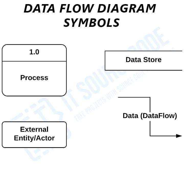
- External Entity: provides or receives information and communicates with the system. They are the origins and destinations of data entering and exiting the system. Entities could also be a third-party company or individual, a computer system, or a business system. The terms used for entities are terminators, sources, sinks, and actors.
- Process: is the part of DFD that modifies data and generates an output. It also executes calculations, sorts data according to logic, or directs data flow according to business standards.
- Data Store: A database table or a membership form are examples of files or repositories that store information for later use. Also, this part requires proper labeling.
- Data Flow: this is the path that the data takes between external entities, processes, and data repositories. It depicts the interface between the other components. Also, a labeled arrow is used to present data flow.
These data flow diagram notations represent the total data handling. Using these Data Flow Diagram symbols would also help to draw attention to the system’s architecture in a simpler way.
Food Ordering System Data Flow Diagram Pdf
You may download the Data Flow Diagram for Food Ordering System PDF by clicking the button below. It has the full details and discussion of the System’s Data Flow Diagram.
You can also modify its content to complete your project requirements and needs.
Conclusion
Levels 0, 1, and 2 of DFD work together to achieve the precise data flow processed by a Food Ordering System.
The context diagram focuses on the ordering system’s broad scope and users. It depicts the entire procedure in a single step to facilitate comprehension of the system’s concept.
DFD level 1 broadens the picture of the primary process by including the food ordering sub-process. This level is beneficial for developers as it stresses the system’s operations.
Levels 0 and 1 describe the food ordering system’s overall concept. In certain plots, users and developers add the DFD level 2 to emphasize the significant processes under the level 1 subprocess.
DFD level 2 is not always required. However, this diagram is used when users need to explain the system operations and DFD in greater detail (data flow diagram).
Official documentation

Mary Grace G. Patulada
Programmer & Technical Writer at PIES IT Solution
Mary Grace G. Patulada (pen name ‘Nym’) is a programmer and writer at PIES IT Solution with a BSIT background from Carlos Hilado Memorial State College, Binalbagan Campus. Authored 370+ UML diagram tutorials and capstone documentation guides at itsourcecode.com. Specializes in UML (class, use case, activity, sequence, component, deployment), DFD, and ER diagrams for BSIT capstone projects.
Expertise: UML Diagrams · DFD · ER Diagrams · Use Case Diagrams · Activity Diagrams · Capstone Documentation · PHP · View all posts by Mary Grace G. Patulada →
Working source code for this system
Download the actual implementation of this system in your preferred language. Each project includes source code, database, and setup instructions for BSIT capstone use.
- PHP: [Complete] Online Food Ordering System In CodeIgniter
- Python: Python Django Online Food Ordering System with Source Code
- Django: Python Django Online Food Ordering System with Source Code
- CodeIgniter: [Complete] Online Food Ordering System In CodeIgniter
- ASP.NET: Online Food Ordering System Project in ASP.net FREE Download
Frequently asked questions
What is a data flow diagram used for in BSIT capstone?
A data flow diagram shows how data moves through the system: processes, data stores, external entities, and data flows. Level 0 (context) shows the whole system as one process; Level 1 breaks it into major sub-processes; Level 2 details each sub-process.
What tool should I use to draw the data flow diagram?
Free options: draw.io (browser-based, saves to Google Drive), Lucidchart free tier, PlantUML (text-based, version-controllable), StarUML (30-day trial then reduced feature set), Visual Paradigm Community Edition. Paid options: Microsoft Visio, Lucidchart pro, Enterprise Architect. For BSIT capstones, draw.io is the most commonly used free tool.
How detailed does the data flow diagram need to be for capstone defense?
Panel members expect the diagram to match the actual system implementation. Include every major class/use case/entity relevant to the system. Omit trivial helper classes. Every diagram element should have a clear justification. Aim for 1-2 diagrams that fully cover the system, not many partial ones.
Should I use black-and-white or colored diagrams?
Black-and-white is standard for capstone documentation to match the thesis format. Use color only if it improves clarity (e.g., grouping subsystems). Ensure text is readable at printed size (10pt minimum for labels).
Where does this diagram go in the capstone documentation?
Chapter 3 (System Design and Methodology) typically holds all UML diagrams. Introduce each diagram with a 1-paragraph description explaining what it shows and how to read it. Reference specific elements in the surrounding text so panel members can follow the design rationale.
can i have a ER diagram of this food ordering system as soon as possible please