Boarding House Finder Thesis Documentation Chapter 3
This Boarding House Finder Thesis Documentation Chapter 3 discusses the research methodology used in the development of the Boarding House Finder.
The software development life cycle is also explained in this chapter.
Here’s the Outline of Boarding House Finder Thesis Documentation Chapter 3 | Methodology
1.System Design
2.Participants of the Study
3.Data Gathering Procedure
4.ISO Software Evaluation
5.Data Analysis and Procedure
6.System Development Life Cycle
7.Context Diagram
8.Data Flow Diagram
9.Functional Decomposition Diagram
10.Use Case Diagram
11.Use Case Description
12.Activity Diagram
13.Entity Relationship Diagram
14.Data Dictionary
15.Screen Layout
16.System Architecture
17.Software and Hardware Specification
18.Gantt chart
19.Time Table
Boarding House Finder Thesis Documentation Chapter 3 : System Design
The research used two types of research methods in the study such as descriptive research and developmental research. It intends to determine the effectiveness of the system “Boarding House Finder”.
The Descriptive Research is used to describe characteristics of a population. Whereas, developmental research has been defined as the systematic study of designing, developing and evaluating instructional programs, processes, and products that must meet criteria of internal consistency and effectiveness.
Boarding House Finder Thesis Documentation Chapter 3 : Participants of the Study
The respondents of the study are the Tenants/users who wanted to find certain location of each boarding houses within their area. The end users include the administrator, expert group and the tenants/users of Boarding House Finder.
Table 2. Participants of the Study and Number of Evaluators
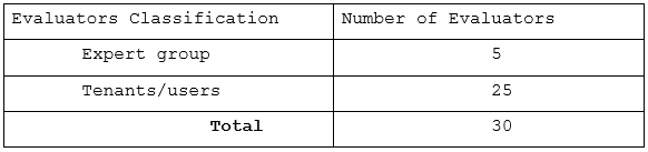
Table 2 shows the classification of evaluators and the corresponding number of evaluators per classification. Five Expert group, Twenty five Tenants/users.
Boarding House Finder Thesis Documentation Chapter 3 : Data Gathering Procedure
The proponents conducted a survey to determine the end users’ evaluation of Boarding House Finder application. One of the proponents distributed the survey questionnaire to the users and instructed the users to rate the developed system based on the criteria stated on the survey form.
The users were given enough time to read, understand, and rate the proposed system. The proponents waited for the users to finish the survey and collected it afterwards for the computation of results.
The evaluation instruments used in the study were ISO Software Evaluation for the experts.
Boarding House Finder Thesis Documentation Chapter 3 : ISO Software Evaluation
ISO Software is a set of technical standards documents for the computer software development processes related business management function.
It is one of the point International Organization for Standardization (ISO) and International Electronical Commission (EIC) Standard which use developed by the ISO and EIC join subcommittee, ISO
Boarding House Finder Thesis Documentation Chapter 3 : Data Analysis and Procedure
To statistically compute the results of the survey questionnaire, the mean statistics are used.
In interpreting the derived weight mean, the hypothetical range with interpretation was applied.
Table 4: Verbal Interpretation
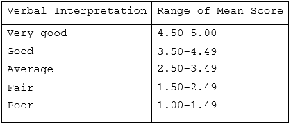
Table 4 shows the verbal interpretation of the corresponding mean scores.
Boarding House Finder Thesis Documentation Chapter 3 : System Development Life Cycle
The system development life cycle is very important when developing a system. It guides developers on the different phases of the project which includes initial planning, requirements gathering, analysis and design, testing, implementation, evaluation and last is deployment.
It is also used by the software industry to design, develop and test high quality software. The SDLC aims to produce high quality software that meets or exceeds customer expectations, reaches completion within times and cost estimates. The life cycle defines a methodology for improving the quality of software and the overall development process.
AGILE METHODOLOGY
The proponents used Agile model of methodology in developing the software which includes the phase of methods such as initial planning, requirements gathering, analysis and design, testing, implementation, evaluation and last is deployment.
Figure 1. Agile Model
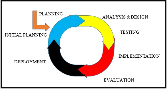
Figure 1 shows the agile model that served as a basis for developing Boarding House Finder Android-based Application.
The proponents use the agile model to develop the propose system that allow to change the requirements when it is needed, enhance quality assurance and provide all the necessary ingredients for the best development of the system.
It is a step by step process to meet goals and objectives of the propose system and to develop a system that provides reliable and secured important records.
Initial Planning
To start the first phase in the project development, the proponents set a meeting for project management of time, cost and scope. In time management, the project schedules are determined the task duration by creating the Gantt chart and time table.
For the cost management, the proponents estimated the expenses that will be used during the development of the project. The project scope management it also applied in the initial planning of project, in part the proponents classify the methods, the scope and limitation of the project and the software and hardware that will be used in the development.
After discussing about the project management the proponents assigning task and work in each member of the team. The proponents are also applied brainstorming and exchanging ideas for additional improvements of the project.
Requirements Gathering
In this phase, the proponent’s conduct an interview to the respondent of the system on what would be the activities that they performed in their daily work and to look for someone possible requirements of the propose project to different sources in order to sure the contents are all accurate.
The developers gather all important suggestion and feedback that will used in developing the project. The proponents conducted research through the internet also to get some related system that could be help in the system. We make sure that all data that has been collected are used for the better result of the project development.
Analysis and Design
The proponents analyzed the information that has been gathered from the respondent for the requirements needed. The possible requirements are combined and analyzed in items of its strengths, weaknesses, and risks, defining the requirements of the second prototype, planning and designing the second prototype, constructing and consulting the second prototype to make the project well functions and to meet the customer satisfaction.
This phase involves the construction of the actual project result, it also defining the overall system architecture. The proponents defined the important features of the project and collaborate the source of coding that will be used in the system.
Testing
In testing phase of the system, the proponents conduct a survey to the IT experts and respondent of the system to fixed some errors and select some additional suggestion. The survey represents as a summary of finding, conclusion and recommendation of the system.
For testing, the proponents know if the system meets the objectives of the study and user satisfaction. After the project reconstruct, the proponents had perform testing and debugging until the final project is working.
Implementation
After a lot of testing made of the proponents for the proposed system, it is now the time for implementation to take place. The proponents implemented the developed system in different desktops or laptops and smartphones.
The proponents also collected the feedbacks of users after they experienced on how to use the propose system. The feedback that has been collected are used for the some changes of the functions and features. But some of their suggestions are not implemented because it is out of our project.
Evaluation
The proponents conduct an evaluation for the acceptance of the user and know if they are satisfied to the propose system. Some of the evaluators give their suggestions and recommendation for the new Improvement of the system.
The gathered feedback from the users and customers through conducting a survey and evaluation weather to consider any changes in the functionalities of the features of system are applied by the developers for the satisfaction of respondents and meet the objectives of the study.
Deployment
In this phase, the proponents take up a final defense to test, if the systems are now ready to used and put into the public. After the final defense the proponents changes some of the function that requested or suggested by the panels to make sure that the system are capable for the deployment in the organization selected.
The proponents make sure that all functions and features are fixed and totally 100% running system. The system will be used with the possible users and maintenance will be part of the developers to be done.
Boarding House Finder Thesis Documentation Chapter 3 : Context Diagram
The context diagram illustrates the overview of the processes involved in the propose Boarding House Finder mobile application.
Figure 2: Context Diagram

Figure 2 above shows the sequence of Boarding House Finder mobile application that being process level 0. The user can search each nearest boarding houses and location by using this application and it will provide a list of it, and also the user can add rate the application from lowest of 1 and highest of 5. The Boarding house Owner can add their boarding houses and updating its availability. The Admin can manage and verify the all activities of boarding houses owner.
Boarding House Finder Thesis Documentation Chapter 3 : Data Flow Diagram
The data flow diagram of Boarding House Finder shown in figure 3 represent the flow of the system through-out the process.
This system will show what kind of information well be input and where the data will go and how it is stored. This diagram shows how the system function.
Figure 3: Data Flow Diagram
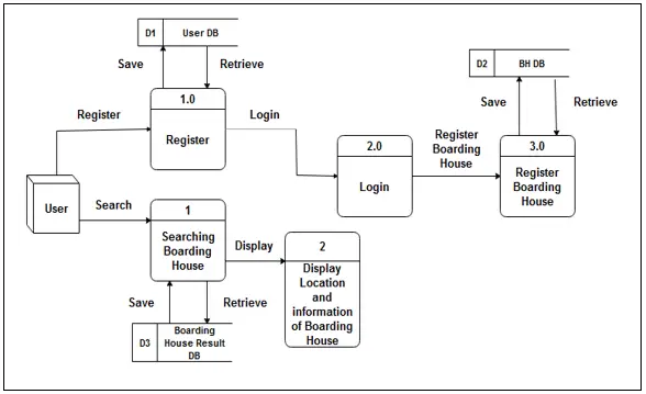
Figure 3 shows the data flow diagram of Boarding House Finder mobile application. The figure represents the flow of the system. The user will sign in or log in in the system and then he/she can be able to find the boarding houses and then generate information back to the system.
Boarding House Finder Thesis Documentation Chapter 3 : Functional Decomposition Diagram
Decomposition diagram shows a high function. Process, organization, data subject area, or other type of object broken down into lower-level, more detailed components of Boarding House Finder.
Figure 4. Functional Decomposition Diagram
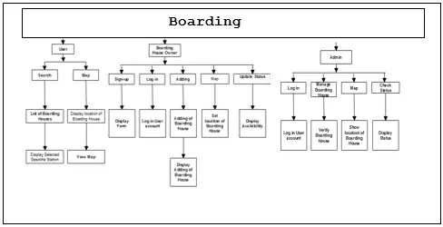
Figure 4 shows the decomposition chart of the Boarding House Finder System. It shows the breakdown of the list of item into or groups on the starting point of the function each items performs.
Boarding House Finder Thesis Documentation Chapter 3 : Use Case Diagram
The diagram below shows the function condition and alternative flow to be met of all entities used.
Figure 5: Use case diagram
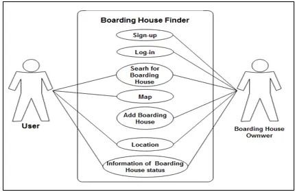
Figure 5 shows the interaction between the system and users, namely the customer and Boarding House Owner. The user access in to the system, show maps, location, and show information of Boarding Houses. The Boarding House Owner can sign-up, add Boarding House and show Boarding House status in to the system.
Boarding House Finder Thesis Documentation Chapter 3 : Use Case Description
The table below describes the interaction between user and Boarding House Owner.
Table 4: Search Boarding House
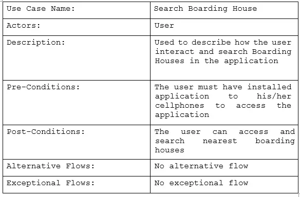
The table 4 describes the functions of entities of search Boarding Houses in system Boarding House Finder.
Table 5: Map
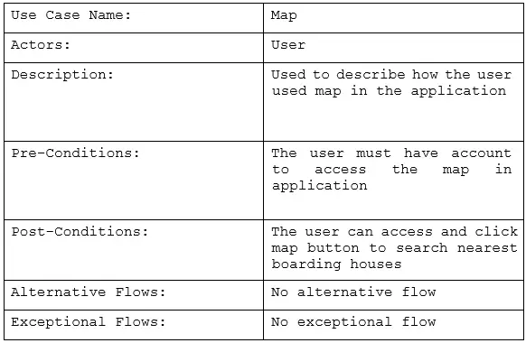
The table 5 describes the functions of entities of mapping in system Boarding House Finder.
Table 6: Location
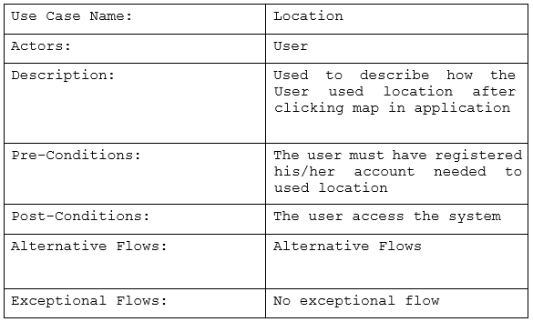
Table 6 describes the function of entities of the location used of users to the system Boarding House Finder.
Table 7: Information of Boarding House status
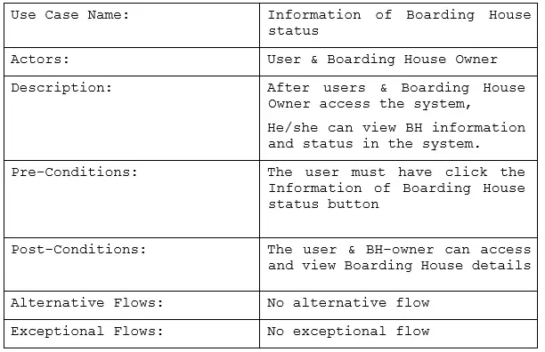
Table 7 describes the function of entities of how the user & BH-owner view boarding house information in the system Boarding House Finder.
Table 8: Add Rate
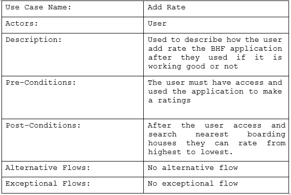
Table 8 describes the function of entities of how the user add rate in the system Boarding House Finder.
Boarding House Finder Thesis Documentation Chapter 3 : Activity Diagram
Activity diagram is the dynamic aspects of the system, the flow chart represents the flow from one activity to another activity.
Table 9: User Activity Diagram
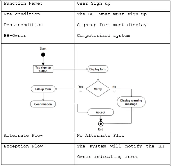
Table 9 shows the execution of activity when the user registers for an account to access, search and locate a boarding houses.
Table 10: Activity Diagram for Admin Log in
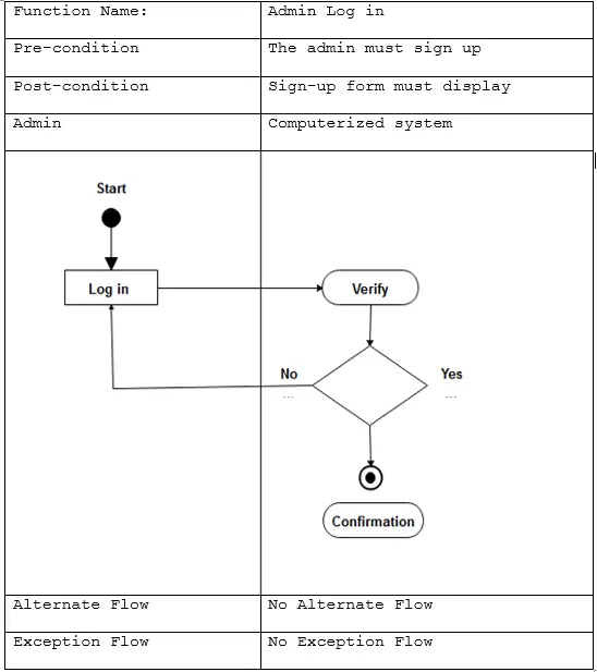
Table 10 shows the activity diagram for admin login. It shows the flow of activities when the admin logs in to the system.
Boarding House Finder Thesis Documentation Chapter 3 : Entity Relationship Diagram
An entity relationship diagram is a graphical representation that includes all the entities in the system and their corresponding relationships.
Figure 7: Entity relationship diagram of the System

Figure 7 shows the entity relationship diagram Boarding house finder. It includes the entities in the system and the relationships of entity sets stored in the database.
Boarding House Finder Thesis Documentation Chapter 3 : Data Dictionary
The data dictionary of Boarding House Finder Reservation System contains the tables used in the system’s database. It is a set of information describing the contents and format of the database. It includes the field name, data type and default value.
Table 11. Autonum Database Table
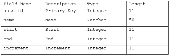
Table 11 shows the data dictionary of the autonum table. The table contains the auto ID, name, start, end, owner’s address, owner’s contact, owner’s email, increment and their corresponding fieldname, description, type and length.
Table 12. Detail Database Table
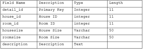
Table 12 shows the data dictionary of the detail table. The table contains the detail id, house id, room id, house size, room size, and their corresponding field names description, type and length.
Table 13. House Database Table
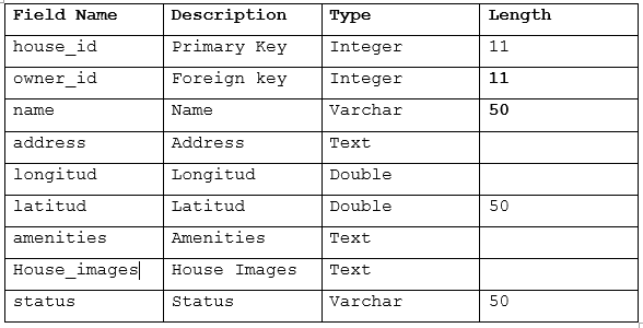
Table 13 shows the data dictionary of the house table. The table contains the house id, owner id, name, address, longitude, latitude, amenities, house images, status and their corresponding field names, description, type and length.
Table 14. Owner Database Table
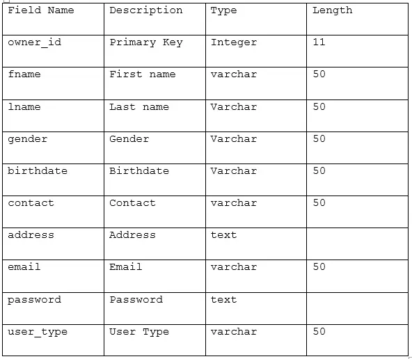
Table 14 shows the data dictionary of the Owner table. The table contains the owner ID, owner’s first name, owner’s last name, user’s gender, user’s birthdate, user’s contact, user’s address, user’s email, user’s password and user type and their corresponding fieldnames description, type and length.
Table 15. Room Database Table
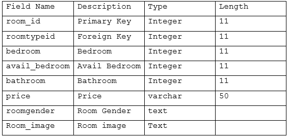
Table 15 shows the data dictionary of the Room table. The table contains the room ID, room type ID, bedroom, avail bedroom, price, room gender, room image, and their corresponding fieldnames description, type and length.
Table 16. Room Type Database Table
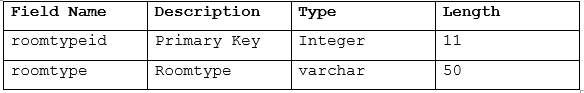
Table 16 shows the data dictionary of the Room Type table. The table contains the room type ID, room type, and their corresponding fieldnames description, type and length.
Table 17. Tenant Database Table
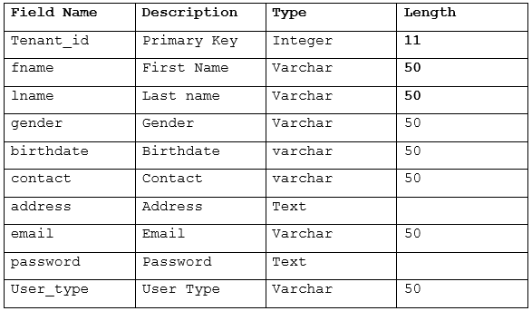
Table 17 shows the data dictionary of the Tenant table. The table contains the room tenant ID, first name, last name, gender, birthdate, contact, address, email, password, usertype, and their corresponding fieldnames description, type and length.
Table 18. User Database Table
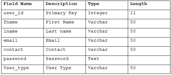
Table 18 shows the data dictionary of the user table. The table contains the user ID, first name, last name, email, contact, password, usertype, and their corresponding fieldnames description, type and length.
Boarding House Finder Thesis Documentation Chapter 3 : Screen Layout
The screen layout of the Boarding House Finder System gives the users an overview of how the interface of what system looks like and what functions are included in the system.
This can help them become familiar with the system’s interface and also provide support in the development of the project.
Figure 7. Home Page
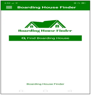
Figure 7 Shows the Home Page of the Boarding Houses Finder.
Figure 8. Search Boarding House Page
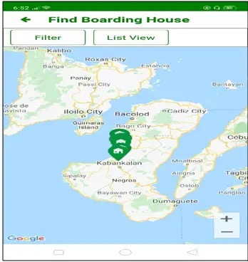
Figure 8 shows the Search Boarding House Page of Boarding House Finder System.
Figure 9: Tenant Create Account Page
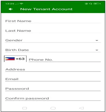
Figure 9 shows the Tenant Create Account Page of Boarding House Finder System.
Figure 10: Owner Create new Account Page
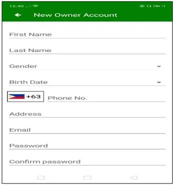
Figure 10 shows the BH-Owner Create new Account Page of Boarding House Finder System.
Figure 11: Log in Page
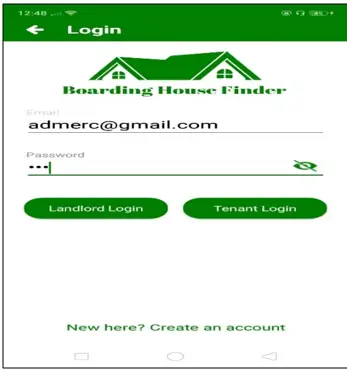
Figure 11 shows the Log in Page of Boarding House Finder System.
Boarding House Finder Thesis Documentation Chapter 3 : System Architecture

Figure 12 shows the operational framework of Boarding House Finder application. The system components include the user, mobile app, internet, admin and database. The users can register using android phones and connected to internet. The admin checks user’s information through internet and the user’s information to be saved to the database. The admin views all transactions through the system.
Boarding House Finder Thesis Documentation Chapter 3 : Software and Hardware Specification
Hardware and Software
The proponent choose the hardware requirements applicable to the development and maintenance of the Boarding House Finder. The application accessed by multiple users through a server.
For development:
Processor: Core I3 or higher, 7th Generation or Higher
RAM: 2Gb Space on disk (at least)
For running on a device:
Device: Phone or tablet running Android Jelly Bean or higher version
Disk space: 30 MB (at the least)
Processor: Dual Core (at the least)
Software Requirements
The proponent used the following software requirements for the development of Boarding House Finder application.
For development:
Operating System: Windows 10 or higher version
Platform: Android SDK Framework 10 or higher version
Software used: MS Word, Paint, Google Maps v2 API, Php, Javascript, MySQL
IDE: B4A
Platform: Android
Text Editor: Sublime Text
Android SDK: API level 10 or higher version
For running on a device:
Operating System: Android Jelly Bean or higher version of mobile phone or tablet with the capacity to accept an inbound and outbound call.
Boarding House Finder Thesis Documentation Chapter 3 : Gantt chart
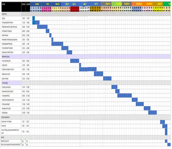
A Gantt chart is a tool used for project time management. It presents the project schedule which includes the activities and their respective start date, end date, duration, and dependencies. The proponents used the Gantt chart to plan, coordinate, and track project activities.
Figure 14: Gantt chart
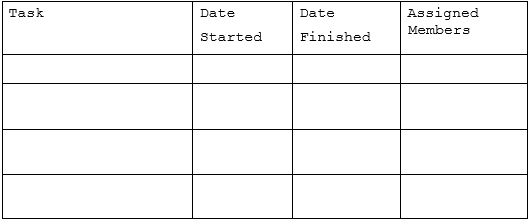
Boarding House Finder Thesis Documentation Chapter 3 : Time Table
This time sample table presents the sequence of the tasks done during the development of the system. It also shows the date started, date finished, and assigned members for each task.
Table 19: Time Table
Related Article
- Boarding House Finder Thesis Documentation Chapter 1
- Boarding House Finder Thesis Documentation Chapter 2
- NOCL Location Based Mobile Application Chapter 3 | Methodology
- Pharmacy Management System Thesis | Chapter 3 – Methodology
- Online Restaurant Management System Documentation Chapter 3
- Sales and Inventory System Documentation Chapter 3
- Library Borrowing System Documentation | Chapter III – Methodology
- Attendance Monitoring System Documentation | Chapter 3
Inquiries
if you have any questions or suggestions about Boarding House Finder Thesis Documentation Chapter 3, please let’s me know by dropping your comment below.