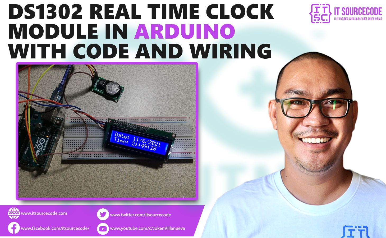
In this article, you will learn how to use a DS1302 real time clock module in Arduino.
Real Time Clock modules are used in many devices like computers, televisions, and many others.
These modules have their own batteries as secondary source of power to keep the time updated.
This article will guide you in connecting the DS1302 real time clock module to the Arduino and display the time on a LCD screen.
DS1302 Real Time Clock Module: Code and Wiring Diagram: Steps in Creating the Device
Here are the steps in creating RFID Door Lock Arduino Project with Data Logging in Python.
- Gathering the Components
The first thing to do is to collect the hardware components for the Arduino device.
Arduino Uno
DS1302 Real Time Clock Module
LCD with I2C interface - Connecting the Components
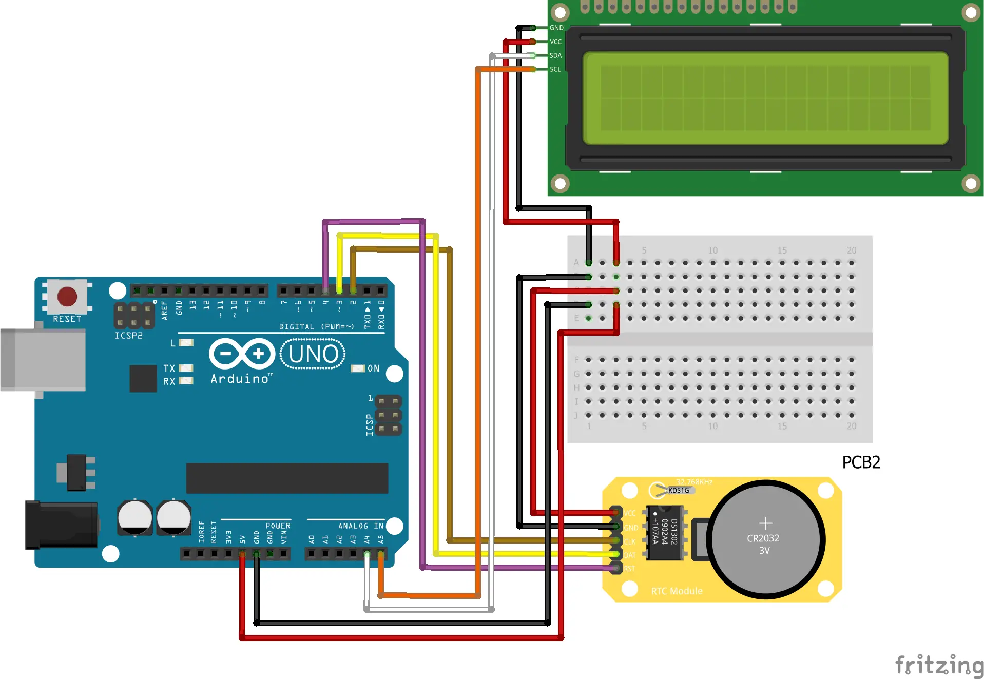
Connect the components to the Arduino Uno. Please refer to the wiring diagram below.
- Coding the Arduino
Third step is about coding the Arduino device.
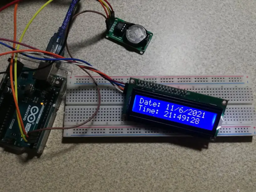
- Upload the Sketch
Final step is uploading the sketch to the Arduino.
DS1302 Real Time Clock Module: Detailed Explanation
Step 1. Gathering the components
To understand the steps above, here is the detailed explanation of the project.
| Quantity | Components |
| 1 | Arduino Uno |
| 1 | DS1302 Real Time Clock Module |
| 1 | LCD with I2C interface |
Arduino UNO
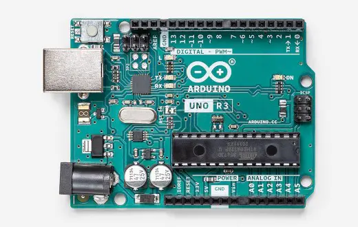
You will be using Arduino Uno for this project. It is an easy to use microprocessor board. Arduino Uno is suitable for any projects and is the cheapest and widely used microprocessor board in the Arduino family. This is great for all kinds of IoT projects.
DS1302 Real Time Clock
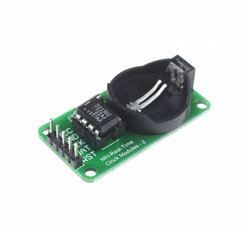
This is a DS1302 RTC module. It has 5 pins – VCC GND, CLK, DAT, and RST. To power the module, it is advised to connect it to the 5V power supply.
Also, you need to add a coin-type battery. This will keep the time updated even if you turn off the device.
16×2 Liquid Crystal Display with I2C
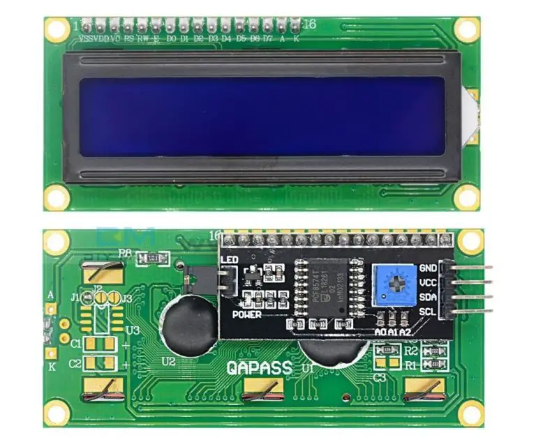
This is where we will display our readings. The LCD that we are using has 16 columns and 2 rows. Also, it comes with an I2C interface.
This means we will only need 4 connections for the power and display. This type of LCD is great if you are planning to connect more modules to the Arduino.
Step 2. Connecting the Components
Now you are ready to connect the components to the Arduino Uno. All components are connected to the 5V pin of the Arduino. The CLK, DAT, and RST pins are connected to the digital pins 2, 3, and 4. The SDA and SCL pins of the LCD are connected to Analog Pins 4 and 5.
Step 3. The Arduino Code
First thing is to download the library for the RTC module. There are many out there but the RTC Virtuabotix Library is used for this project.
Other updated libraries have more functions for more advanced projects. For now, this library will suffice our needs.
Copy the code below to a new sketch in the Arduino IDE. Once done, you can upload it to the Arduino Uno.
#include "virtuabotixRTC.h"//Library used
#include <LiquidCrystal_I2C.h>

LiquidCrystal_I2C lcd(0x27, 16, 2);
virtuabotixRTC myRTC(2, 3, 4); //The order here is DAT,CLK,RST. You can change this depending on the wiring

char timeChar[8]; //number of digits for the format


void setup() {

 lcd.init();
 lcd.backlight();

 // Set the current date, and time in the following format:
 // seconds, minutes, hours, day of the week, day of the month, month, year
 myRTC.setDS1302Time(15, 22, 21, 7, 11, 6, 2021); //Here you write your actual time/date as shown above
 //but remember to "comment/remove" this function once you're done
 //The setup is done only one time and the module will continue counting it automatically
}

void loop() {
 myRTC.updateTime();

// Start printing elements as individuals
 lcd.setCursor(0,0);
 lcd.print("Date: ");
 lcd.print(myRTC.dayofmonth); //You can switch between day and month if you're using American system
 lcd.print("/");
 lcd.print(myRTC.month);
 lcd.print("/");
 lcd.print(myRTC.year);

 lcd.setCursor(0,1);
 sprintf(timeChar, "Time: %02d:%02d:%02d",myRTC.hours, myRTC.minutes, myRTC.seconds);
 lcd.print(timeChar);
 delay(1000);

}
A problem I encountered is the formatting of the seconds. As the RTC seconds reach double digits, the last digit retains as it cycles back to 0. Therefore instead of displaying “0” , it displays “09, 19, 29, 39 …” and so on.
To fix that, I used the sprintf() to give a double digit format.
Step 4. Upload the sketch
Now the device can operate on its own.
Conclusion
So there you have it! DS1302 Real Time Clock Module. This project is intimidating at first but you will see that it is fairly easy to do. You can combine this to other Python or Arduino projects and build an awesome system!
Click the button below to download the entire project.
Download
Related Articles
Inquiries
Feel free to write your questions about the DS1302 Real Time Clock Module in the comments below.