In this article, you will learn how to wire and code an Arduino-Controlled Light Switch. The project will let you control a lamp using an Infrared Remote control and a relay module.
By pushing a button, you can turn on or off a lamp – just like a television.
Here are the steps in creating the project.
Arduino Remote Control Light Switch: Steps in Creating the Device
Here are the steps in creating Temperature Monitoring System using Arduino..
- Gathering the Components
The first thing to do is to collect the hardware components for the Arduino device.
Arduino Uno
IR Receiver and remote
Single Channel Relay Module
LED light bulb connected to a wall socket - Connecting the Components
Connect the components to the Arduino Uno. Please refer to the wiring diagram below.
- Coding the Arduino
Third step is about coding the Arduino device to work with the components.
- Upload the Sketch
Lastly, upload the sketch to the Arduino.
Relay Module Connection in Arduino: Detailed Explanation
To start this project, you need the following:
| Qty | Component |
| 1 | Arduino UNO |
| 1 | IR receiver and Remote |
| 1 | Single Channel Relay Module |
| 1 | LED bulb |
Arduino UNO
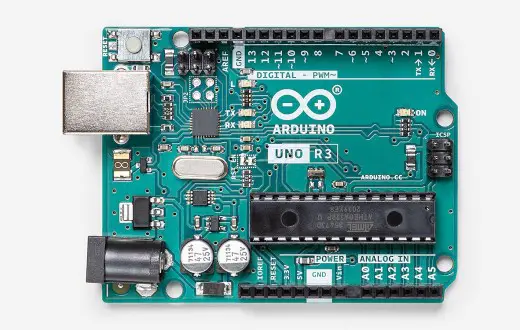
For this project, we will be using an Arduino Uno microprocessor board. Arduino Uno is suitable for any projects and is the cheapest and widely used microprocessor board in the Arduino family. This is great for all kinds of IoT projects.
IR Receiver
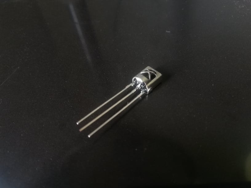
This project uses a standalone IR receiver diode. The first pin is connected to the digital pin of the Arduino. The long pin is the ground connection and the last pin is the Vcc.
IR Remote Control

This is an IR remote control. IR pulses are transmitted by the remote that is converted to a HEX code. Each button has its own HEX code. If the button is pressed continuously, the HEX code will be 0xFFFFFFFF.
For a complete guide in infrared remote control project, click here.
Single Channel Relay Module
This project uses a single channel relay module. There are other relay modules available. You can use 2-channel or 3-channel, it simply depends on the project requirements.
The single relay module below is rated to switch a single high-powered device from the Arduino. It can switch up to 10 amperes with 250 volts of AC or 30 volts of DC.
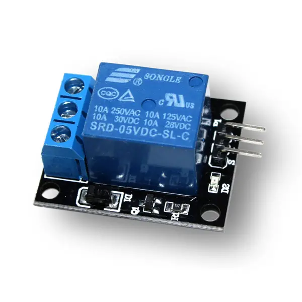
This module has 3 pins – Signal, Power, and Ground. The output terminals are COM, NO, and NC.
The middle terminal is the COM. This is where you connect signal you want to switch (example: electricity).
The bottom terminal is the Normally Closed terminal. This terminal is used if you want to turn off your relay by default. On the other hand, the top terminal is the Normally Open terminal.
This is the opposite of the other terminal. You can connect here if you want your relay to be open by default.
PLEASE BE CAREFUL IN WIRING. HIGH POWERED ELECTRICITY IS INVOLVED.
Schematic Diagram
Here is the wiring diagram arduino remote control light switch. The red wire of the lamp is connected to the COM terminal and to NO terminal of the relay. The relay itself is powered using the 5V power of the Arduino. Signal pin of the relay is connected to the digital pin 6 of the Arduino.
The IR receiver is connected to the digital pin 7 of the Arduino.

AGAIN, PLEASE BE CAREFUL IN WIRING. HIGH POWERED ELECTRICITY IS INVOLVED.
Code
First is to download the library needed for the project. The “IRremote” library is used here and you can download it using the Arduino Library Manager. Open “Tools>Manage Libraries” and search for “IRremote”. Just install and wait for it to finish.
For the code, objects for IRrecv and decode_results are created. Declare the data pin of the module and the IR .
Then for the setup, simply set the pin mode of the declared variable to OUTPUT and enable the IR receiver.
In the loop function, if the Arduino receives a signal for button “1”, the relay will switch to on. It will turn off the light by pressing “0”.
#include <IRremote.h>

int RelayPin = 6;

const int RECV_PIN = 7;

IRrecv irrecv(RECV_PIN);
decode_results results;


void setup() {
 // Set RelayPin as an output pin
 pinMode(RelayPin, OUTPUT);
 irrecv.enableIRIn();

 digitalWrite(RelayPin, LOW);

}

void loop() {
  if (irrecv.decode(&results)){
    switch(results.value){
      case 0xFF30CF: //Keypad button "1"
        digitalWrite(RelayPin, HIGH);

    }

    switch(results.value){
      case 0XFF6897: //Keypad button "0"
        digitalWrite(RelayPin, LOW);
    }
      irrecv.resume();
  }
}
Connect your lamp to a wall socket, Double-check the wiring. PLEASE BE CAREFUL IN WIRING THE PROJECT. After that, upload the code to the Arduino.
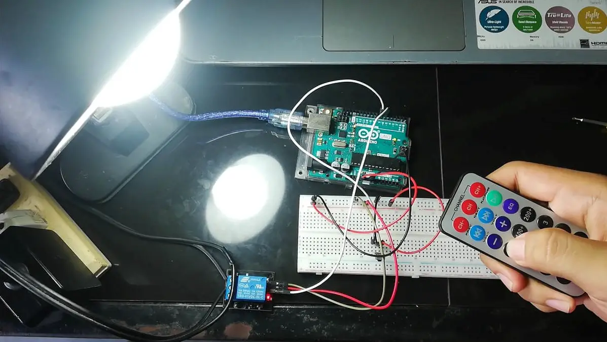
Output
Now try out your arduino remote control light switch.
Summary
So there you have it – an Arduino Remote Control Light Switch. This device is simple to create and can be used in other projects as well. You can always add more sensors to the device, upgrading it to a much-sophisticated device.
Download
Click the button below to download the source code.
Related Articles
Inquiries
Feel free to write your questions about the project at the comments below.