
Component Diagram for Event Management System
The component diagram for event management system is used to show how the parts of the card processing system work together to make the system operate correctly. This diagram visualizes the software’s parts, how are they organized, and how they depend on each other. This gives a high-level look at the parts of a system.
The components of event management system component diagram could be a part of software or hardware. They could be a database, a user interface, or something else that helps the processing system work.
Event Management System Component Diagram: Table of contents
- Component Diagram for Event Management System
- Component Diagram for Event Management System: Details
- What is the Purpose of the Event Management System?
- What is the Event Management System Component Diagram in UML?
- The Component Diagram for Event Management System
- Event Management System Component Diagram (Explanation)
- Event Management System Component Diagram Pdf
- Characteristics of Component Diagram:
- Benefits of using Component Diagram
- Steps in Developing Component Diagram
- Conclusion
- Related Articles:
- Recommended Articles:
- Inquiries
Component Diagram for Event Management System: Details
The table shows the basic details of the component diagram of event management system. It has quick description details of the component diagram illustration.
| Name: | Event Management System Component Diagram |
| Abstract: | The event management system UML component diagram is used in object-oriented programming to group classes together based on their common purpose. This way, the developer and others can see how a project is progressing at a high level. |
| UML Diagram: | Component Diagram |
| Users: | system Admin, Users, and Clients |
| Tools Used: | Diagraming Tools that have UML Component Diagram Symbols |
| Designer: | ITSourceCode.com |
What is the Purpose of the Event Management System?
An Event Management System (or Event Management Software) assists event planners in planning, executing, and reporting events, resulting in increased commercial success.
The event management system project will update event records, participant records, all event expenditures, and staff and employee records. It will also preserve a record of the specific occurrence and previous events that have occurred.
What is the Event Management System Component Diagram in UML?
A component diagram in the (UML) Unified Modeling Language shows how parts are wired together to explain the parts of the event management system. They are used to show the structure of any kind of system.
The UML component diagram shows how the card processing system comprises a set of deployable components, such as dynamic-link library (DLL) files, executable files, or web services. Using well-defined interfaces, these parts communicate with each other and keep their internal details hidden from each other and the outside world.
The Component Diagram for Event Management System
This component diagram of event management system is the illustration of the components of every hardware and software node. The component diagram below is a detailed illustration of other UML diagrams for the System.
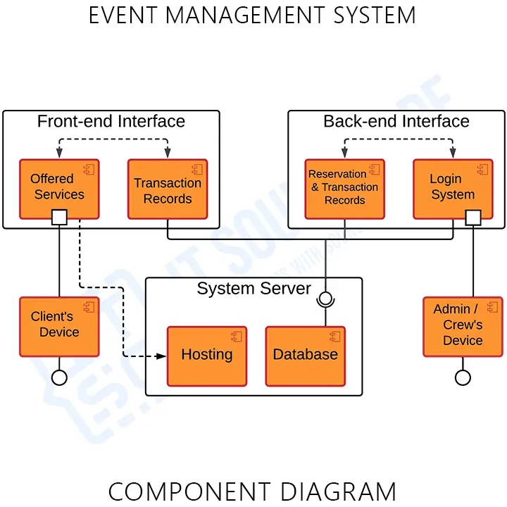
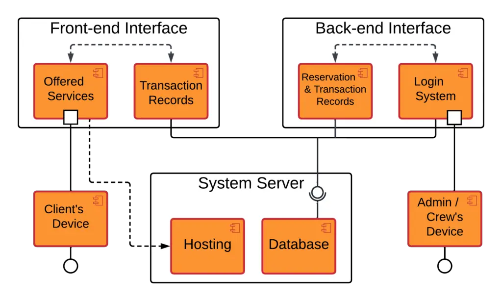
This component diagram shows the structure of the event system, which consists of the software components and their interfaces, user information, and the database. Their dependencies explain how they work together. You can use a component diagram to show how software systems work at a high level, or you can use them to show how each component works at a lower level, like in a package.
Event Management System Component Diagram (Explanation)
The Event Management System UML component diagram explains the sketch of the required software and hardware components and the dependencies between them. These components are labeled to clarify their part in the system’s operation. They were represented by symbols that explain their function and role in the overall processing system operation.
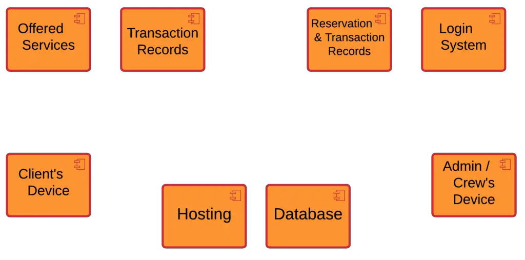
The system’s component diagram has 9 components. Each of these components has its part in the event management system. The system’s components were the client’s device, admin/crew’s device, system database, ticket reservation interface, list of reservations, list of reserved tickets, list of pending reservations, system dashboard, and login interface.
This diagram shows several interfaces that are provided and required. The dependencies on each component are explained through the lines and arrows drawn in the diagram. The required and provided interfaces were declared by the line that has a circle with a semi-circle head.
Event Management System Component Diagram Pdf
You may download the Component Diagram PDF file by clicking the button below. It has the full details and discussion of the system’s component diagram. You can also modify its content to complete your project requirements and needs.
Characteristics of Component Diagram:
- In component-based development, they describe systems that have a service-oriented architecture.
- It shows how the code itself looks.
- It can be used to focus on the relationship between the parts while hiding the specifics.
- Help stakeholders understand how the system being built works and how it will be used.
Benefits of using Component Diagram
As complicated as it looks, the component diagram is very important when you’re building your system because it shows how everything works together. Here are the benefits of designing the event management system component diagram:
- Imagine how the system looks in real life.
- Pay attention to the system’s parts and how they work together.
- Pay attention to how the service behaves when it comes to the interface.
Steps in Developing Component Diagram
Time needed: 10 minutes
Here are the steps in developing the event management system component diagram.
- Finalize the Function and Processes of the Software
The first step in developing the component diagram is finalizing the processes and functions of the software. This activity will help programmers analyze what are the things needed to complete the event management process. Then the finalized processes or functions will be the base concept in designing the system’s component diagram.
- Put the Components included
A component is a piece of the system that makes sense in terms of logic. It’s a little more abstract than classes. There are tabs or the word “Component” written on top of the name of the component to help you tell it apart from a class.

The component symbol is used for a person or thing that needs to do a stereotype function. It gives and takes behavior through interfaces, as well as through other parts. Components can be grouped into a node or another component and can be only one component. - Add the Dependencies (Ports and interfaces)
A dependency is a relationship in which one component needs the information and services of another component, but not always the other way around. To show that one component is relying on another, you should make a connection.

The component’s port is a feature that indicates where the component and its environment meet. In this picture, ports are shown in small squares on the sides of classifiers. It is created when one thing is needed for another thing to work. There is an “include” statement in the makefile for the component that is dependent on the other component.
Interfaces show how components are wired together and how they work together. When a component needs a certain interface, the assembly connector lets you connect it to another component that already has that interface. It looks like a semi-circle and a line.
A component list contains the set of interfaces that a component can use or realize. Components also need interfaces to do their job. It is part of a system that protects the things inside. They are the parts of a system that make sense and play a big part in how a system works.
Conclusion
You need to know the diagrams used to design and develop the Event Management System. This method is to perfectly create a fully-functional system without unwanted errors and avoid mistakes in development. A component diagram will help you know the components of software and hardware that the project should possess. Not only that, you will find out the needed consideration for the software to work perfectly.
The component diagram shows how a system is put together. During the design phase, software artifacts (classes, interfaces, etc.) of a system are put together into different groups based on how they work together. Now, these groups of things are called parts. Check out our Related and Recommended Articles for more Learning and Information.
Related Articles:
- Component Diagram for Login System
- Component Diagram for Attendance Management System
- Component Diagram for Face Recognition System
- Component Diagram for Course Registration System
- Component Diagram for Point of Sale System
Recommended Articles:
Inquiries
If you have inquiries or suggestions about the discussion and illustration for the Component Diagram for Event Management System, just leave us your comments below. We would be glad to hear to concerns and suggestions and be part of your learning.
Keep us updated and Good day!
Official documentation
Working source code for this system
Download the actual implementation of this system in your preferred language. Each project includes source code, database, and setup instructions for BSIT capstone use.
Frequently asked questions
What is a component diagram used for in BSIT capstone?
A component diagram shows the system’s software architecture: components (modules or packages) and their dependencies. It goes in Chapter 3 and communicates how the system is decomposed into deployable units.
What tool should I use to draw the component diagram?
Free options: draw.io (browser-based, saves to Google Drive), Lucidchart free tier, PlantUML (text-based, version-controllable), StarUML (30-day trial then reduced feature set), Visual Paradigm Community Edition. Paid options: Microsoft Visio, Lucidchart pro, Enterprise Architect. For BSIT capstones, draw.io is the most commonly used free tool.
How detailed does the component diagram need to be for capstone defense?
Panel members expect the diagram to match the actual system implementation. Include every major class/use case/entity relevant to the system. Omit trivial helper classes. Every diagram element should have a clear justification. Aim for 1-2 diagrams that fully cover the system, not many partial ones.
Should I use black-and-white or colored diagrams?
Black-and-white is standard for capstone documentation to match the thesis format. Use color only if it improves clarity (e.g., grouping subsystems). Ensure text is readable at printed size (10pt minimum for labels).
Where does this diagram go in the capstone documentation?
Chapter 3 (System Design and Methodology) typically holds all UML diagrams. Introduce each diagram with a 1-paragraph description explaining what it shows and how to read it. Reference specific elements in the surrounding text so panel members can follow the design rationale.

Mary Grace G. Patulada
Programmer & Technical Writer at PIES IT Solution
Mary Grace G. Patulada (pen name ‘Nym’) is a programmer and writer at PIES IT Solution with a BSIT background from Carlos Hilado Memorial State College, Binalbagan Campus. Authored 370+ UML diagram tutorials and capstone documentation guides at itsourcecode.com. Specializes in UML (class, use case, activity, sequence, component, deployment), DFD, and ER diagrams for BSIT capstone projects.
Expertise: UML Diagrams · DFD · ER Diagrams · Use Case Diagrams · Activity Diagrams · Capstone Documentation · PHP · View all posts by Mary Grace G. Patulada →