
Tools and Equipment Monitoring System Methodology
This Tools and Equipment Monitoring System Methodology presents the system design of the proponent’s system.
SYSTEM DEVELOPMENT LIFE CYCLE (SDLC)
The Software Development Life Cycle (SDLC) is very important in developing the system since it can help us to know how to use a process for planning, requirements analysis, testing, evaluation and deploying an information system.
The SDLC is used as a guide in developing the project, planning and analyzing in which the processes are in step by step procedures.
The concept of SDLC applies to a range of hardware and software configurations, as a system can be composed of hardware and software only, or a combination of both.
This space is done by step by step and was used repeatedly to accomplish the final project.
RAPID APPLICATION DEVELOPMENT METHODOLOGY
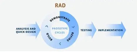
Figure 1: Rapid Application Development Methodology
Figure 1 tells from the beginning of the research up to the last process. RAD model distributes the analysis, design, build and test phases into a series of short, iterative development cycle. RAD makes heavy use of prototyping to make sure interested parties have a clear picture of all aspects of the system.
Rapid Application Development is easy to use as a methodology the diagram shows the step by step so that the problems that might encounter can be polished by reviewing every step.
In RAD, the functions are developed as the prototype is being integrated to make the complete process quicker it makes it easier to incorporate and understand the changes within the development.
Analysis and Quick Design
In this phase, the proponents analyzed the data they gathered and created a design that is suitable for the processed for Tools and Equipment Monitoring System.
Business Modeling
This phase of software development is the stimulant of the proponents to plan a software that will aid the construction company. The proponents conducted an interview and observations on how the staff doing their job in a period of time.
Then, proponents asked for the process they’re doing manual when it comes to inventory and the proponents found out a problem and a need that can be addressed by the proponent’s system.
Then proponents had sited different platforms to be used for the entire development of the system that can attain the objectives of the study.
Data Modeling
In this phase, the information that has been gathered from business model is being analyzed to form a set of data objects deemed very important all throughout the process for developing a system.
The relation between these data objects are established and defined in detail in relevance to the business model.
Design Modeling
In this phase, the proponents developed a design which is user-friendly and can obtain an easy access to the field requested by the user and since one of the features of the system is web-hosted, proponent used the standard mark-up language for creating web-site or the HTML, and for the design or the CSS.
Process Modeling
In this phase, the data object sets are being executed to start the first process which is establishing the business information flow needed to achieve specific business objectives as per the business model.
The process model for any changes or enhancements to the data object set is defined in this phase.
In line with this stage of development, the proponents had created some of the methods for the system’s processes, however the proponents had been encountered some problems while developing these processes. Yet by the availability of the information on the internet.
And in agreement to this stage, the proponents had also sought for some of the further inputs vital to the system and formulate further processes. Furthermore, knowledge in programming and logic were really needed to attain this stage.
Application Generation
Generating the actual system is being describe in this phase, by using automation tools for the process to be converted into actual prototype.
The over-all development of the system in both front-end and back-end has been developed using PHP since PHP file contain text, HTML, CSS, JavaScript and PHP code.
The proponents used this platform via Sublime Text Editor and for the database of the system, the proponents had used Structured Query Language specifically MYSQL using PHPMyAdmin.
But during the development of the system the proponents used local hosting using XAMPP- Apache Server.
Testing and Implementation
This phase is the actual testing of the actual prototype, to be able to fix suddenly if there is an error found. The overall testing time is reduced in the RAD model as the prototype is independently tested during iterations.
At this stage, the proponents will conduct a series of testing of the system to the user, however, in every test done by the proponents, the user/s suggest further changes of lay-out of the system. The proponents took a lot of testing and checking until it reaches the maximum user’s satisfaction.
Data Gathering Procedure
The proponents conducted a survey to determine the end users’ evaluation of Tools and Equipment Monitoring System. Proponents distributed the survey questionnaire to the users and instructed the users to rate the developed system based on the criteria stated on the survey form.
Research Instrument
Tools and equipment monitoring system use the PSSUQ Questionaire it is widely used to measure users’ perceived satisfaction of a website.
Respondent of Study
The respondents of the study are the person who are working in the construction companies for the user evaluation and for the expert we have IT expert inside the campus.
Table 2: Respondents of the study
| Respondent | Number of Respondents |
| User | 15 |
| Expert | 5 |
| Total of Respondents | 20 |
Table 2 shows the respondents of the proposed system
Analysis of Data
Proponents use this scale to interpret the results of user and expert evaluation.
1.00-2.19 Very Useful
2.20-3.39 Useful
3.40-4.59 Moderately Useful
4.60-5.79 lesds Useful
5.80- Least Useful
Tools and Equipment Monitoring System Use Case Model
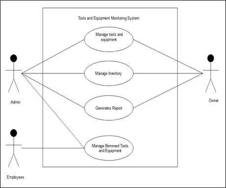
Figure 2: Tools and Equipment Monitoring System Use Case Diagram
Figure 2 shows the use case of Tools and Equipment Monitoring System and the task of every actors of the system.
Manage Tools and Equipment
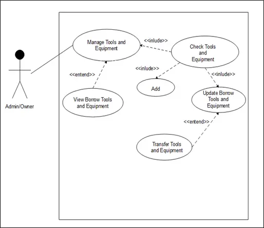
Figure 3: Manage Tools and Equipment Use Case Diagram
Figure 3 shows Manage Tools and Equipment Use Case Diagram and how the actors manage the tools and equipment of the Constructions Company.
Table 3: Manage Tools and Equipment Use Case Description of Construction Company and Tools and Equipment Monitoring System.
| Use Case Name: | Manage Tools and Equipment | |
| Actors: | Admin/Owner | |
| Description: | This use case describes how the admin and the owner manages the tools and equipment. | |
| Pre-conditions: | The admin and owner is logged into the System. | |
| Post-conditions: | Admin and Owner has received an acknowledgement from the system that the transaction was successful or if not complete, a message explaining the failure | |
| Normal Flow: | Actor | System |
| Admin/Owner check the tools and equipment.Admin check the availability of tools and equipment.Admin add new borrowed tools and equipment. Admin update borrowed tools and equipment.Admin transferred borrowed heavy equipmentAdmin/Owner view all borrowed | System display all the list of tools and equipment.System display the list of available tools and equipment.System invokes add new borrowed and display form.System invokes update borrowed and display form.System invokes transferred borrowed heavy equipment and display form.System display all the tools and equipment details that has been borrowed. | |
| Alternative Flows: | The admin and owner should check the tools and equipment in order to avoid problems | |
| Business Rules: | System shows the list of borrowed tools and equipment |
Manage Inventory

Figure 4: Manage Inventory Use Case Diagram
Figure 4 shows Manage Inventory Use Case Diagram and how the actors Manage the Inventory of Construction Company.
Table 4: Manage Inventory Use Case Description of Construction Company and Tools and Equipment Monitoring System.
| Use Case Name: | Manage Inventory | |
| Actors: | Admin/Owner | |
| Description: | This use case describes how the Admin and Owner Manage the Inventory. | |
| Pre-conditions: | The admin/owner is logged into Tools and Equipment Monitoring System. | |
| Post-conditions: | Admin and Owner has received an acknowledgement from the system that the transaction was successful or if not complete, a message explaining the failure | |
| Normal Flow: | Actor | System |
| Admin/Owner check the tools and equipment.Admin/Owner check the borrowed tools and equipment.Admin/Owner check the transferred equipment.Admin/Owner check the returned tools and equipment. | System display the list of tools and equipment. System will display all the borrowed tools and equipment and details.System display the list of transferred equipment.System display the list of returned tools and equipment. | |
| Alternative Flows: | Admin and Owner should check first all the transactions. | |
| Business Rules: | System shows the list of borrowed tools and equipment. |
Generates Report
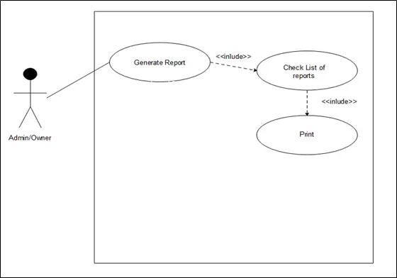
Figure 5: Generates Report Use Case Diagram
Figure 5 shows Generates Report Use Case Diagram and how the actors Generates Reports of Construction Company.
Table 5: Generates Report Use Case Description of Construction Company and Tools and Equipment Monitoring System.
| Use Case Name: | Generates Report | |
| Actors: | Admin/Owner | |
| Description: | This use case describes how the admin/owner generates the report by checking all the reports. | |
| Pre-conditions: | The admin/owner is logged into the System. | |
| Post-conditions: | Admin and Owner has received an acknowledgement from the system that the transaction was successful or if not complete, a message explaining the failure. | |
| Normal Flow: | Actor | System |
| Admin and the Owner view all the records.Admin and the Owner print the report. | System display all records. System will print the report. | |
| Alternative Flows: | Admin and Owner should check first all the transactions. | |
| Business Rules: | System shows the list of borrowed tools and equipment. |
Manage Borrow Tools and Equipment
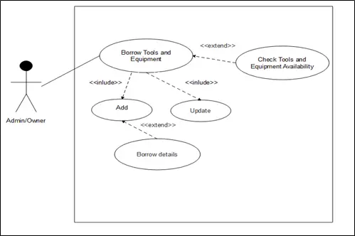
Figure 6: Manage Borrow Tools and Equipment Use Case Diagram
Figure 6 shows Manage Borrow Tools and Equipment Use Case Diagram and how Borrowed of Tools and Equipment of Construction Company.
Table 6: Borrowed Tools and Equipment Use Case Description of Construction Company and Tools and Equipment Monitoring System.
| Use Case Name: | Borrowed Tools | |
| Actors: | Admin/Employees | |
| Description: | This use case describes how the Admin manages the Employees by checking the available tools and equipment | |
| Pre-conditions: | The admin is logged into the System. | |
| Post-conditions: | Admin and cashier has received an acknowledgement from the system that the transaction was successful or if not complete, a message explaining the failure | |
| Normal Flow: | Actor | System |
| Admin check the available tools and Equipment.Admin add new Borrow tools and equipment.Admin save the records of newly borrowed tools and equipment.Admin check the borrowed details. | System display the available tools and equipment.System invokes add new borrow tools and equipment and display form.System invokes successfully save new borrowed tools and equipment.System display the new added transactions. | |
| Alternative Flows: | Admin and Owner should check first all the transactions. | |
| Business Rules: | System display all the employees records. |
ACTIVITY DIAGRAMS
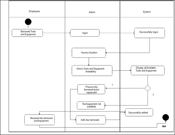
Figure 7: Activity Diagram for borrowing
Figure 7 shows the activity diagram for ordering and the steps in borrowing.
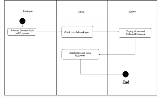
Figure 8: Activity Diagram for returning of borrowed tools/equipment
Figure 8 shows the activity diagram for ordering and the steps in borrowing.
Context Diagram
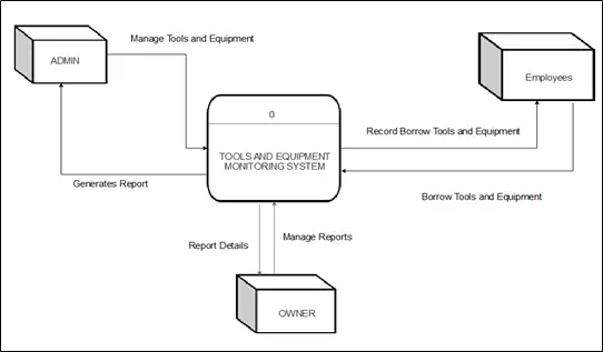
Figure 9: Context Diagram (Level 0 DFD)
Data Flow Diagram
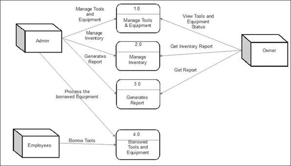
Figure 10: Data Flow Diagram (Level 1)
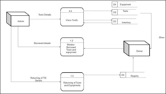
Figure 11: Data Flow Diagram of Manage Tools & Equipment (Level 1)
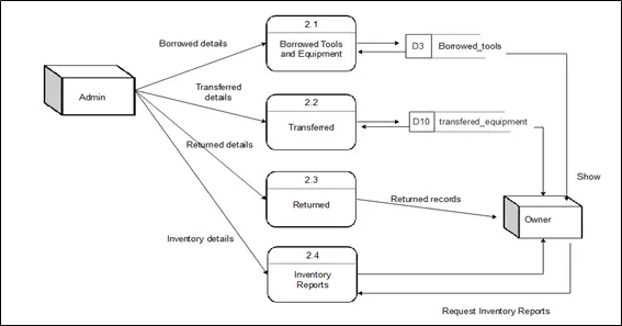
Figure 12: Data Flow Diagram of Manage Inventory (Level 2)
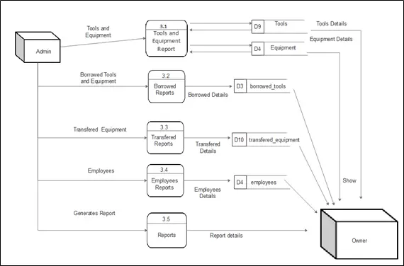
Figure 13: Data Flow Diagram of Generates Report (Level 2)
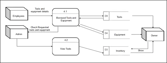
Figure 14: Data Flow Diagram of Borrowing of Tools and Equipment (Level 2)
Entity Relationship Diagram
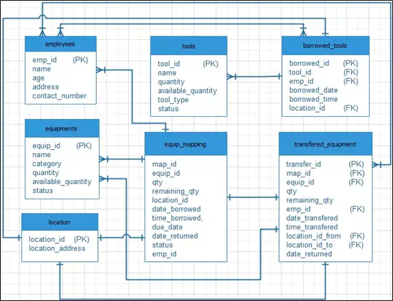
Figure 15: Entity Relationship Diagram
Data Dictionary
Table 7: tbladmin
| Field Name | Description | Type | Length |
| user_id | user_id PK | int | 11 |
| name | Name | varchar | 30 |
| username | Username | varchar | 30 |
| password | Password | text | |
| user_type | User Type | varchar | 30 |
Table 7 is the table for admin. It shows the important data given for admin.
Table 8: tblauto
| Field Name | Description | Type | Length |
| auto_id | Auto number id PK | int | 11 |
| auto_start | Auto number start | int | 11 |
| auto_end | Auto number end | int | 11 |
| increment | Increment | int | 11 |
| description | Description | varchar | 30 |
Table 8 is the table for auto number of tools and equipment. It shows the important data given which the admin can easily identify borrowed tools and equipment.
Table 9: tblborrowedtools
| Field Name | Description | Type | Length |
| borrow_id | Borrowed id PK | int | 11 |
| tool_id | Tool id | int | 11 |
| emp_id | Employee id | int | 11 |
| borrowed_date | Borrowed date | varchar | 30 |
| borrowed_time | Borrowed time | varchar | 30 |
| location_id | Location id | int | 11 |
Table 9 is the table for borrowed tools. It shows the important data given by the borrower which the admin can use.
Table 10: tblemployeees
| Field Name | Description | Type | Length |
| emp_id | Employee id PK | int | 11 |
| name | Employee name | varchar | 30 |
| age | Employee age | varchar | 3 |
| address | Employee address | text | 50 |
| contact_number | Employee contact number | varchar | 30 |
Table 10 is the table for employees. It shows the important data given by the employees.
Table 11: tblequipments
| Field Name | Description | Type | Length |
| equip_id | Equipment id PK | int | 11 |
| name | Equipment name | varchar | 30 |
| category | Equipment category | varchar | 30 |
| quantity | Equipment quantity | int | 11 |
| available_quantity | Equipment’s available quantity | int | 11 |
| status | Equipment Status | varchar | 30 |
Table 11 is the table for equipment’s. It shows the important data given for equipment’s.
Table 12: tblequipmapping
| Field Name | Description | Type | Length |
| map_id | Map id PK | int | 11 |
| equip_id | Equipment id | int | 11 |
| qty | Equipment quantity | int | 11 |
| remaining_qty | Equipment remaining quantity | int | 11 |
| location_id | Location id | int | 11 |
| date_borrowed | Date borrowed | varchar | 30 |
| time_borrowed | Time borrowed | varchar | 50 |
| due_date | Due date | varchar | 30 |
| date_returned | Date returned | varchar | 30 |
| status | Equipment status | varchar | 30 |
| emp_id | Employee id | int | 11 |
Table 12 is the table for equip mapping. It shows the important given data.
Table 13: tbllocation
| Field Name | Description | Type | Length |
| location_id | Location id PK | int | 11 |
| location_address | Location address | text |
Table 13 is the table for location. It shows the important data given for location.
Table 14: tbltemp
| Field Name | Description | Type | Length |
| temp_id | Temporary id | int | 11 |
| equip_id | Equipment id | Int | 11 |
| qty | Quantity | Int | 11 |
| emp_id | Employee id | Int | 11 |
| location_id | Location id | Int | 11 |
| unique_id | Unique id | varchar | 30 |
Table 14 is the table for location. It shows the important data given for location.
Table 15: tbltools
| Field Name | Description | Type | Length |
| tool_id | Tool id PK | int | 11 |
| name | Tools name | varchar | 11 |
| quantity | Tools quantity | int | 11 |
| available_quantity | Tools available quantity | int | 11 |
| tool_type | Tools Type | varchar | 11 |
| status | Tools status | varchar | 30 |
Table 15 is the table for tools. It shows the important data given for tools.
Table 16: tbltransferredequipment
| Field Name | Description | Type | Length |
| transfer_id | Transfer id PK | int | 11 |
| map_id | Map id | int | 11 |
| equip_id | Equipment id | int | 11 |
| qty | Quantity | int | 11 |
| remaining_qty | Remaining quantity | int | 11 |
| emp_id | Employee id | int | 11 |
| date_transfered | Date transfered | varchar | 30 |
| time_transfered | Time transfered | varchar | 30 |
| location_id_from | Location id from | int | 11 |
| location_id_to | Location id to | int | 11 |
| date_returned | Date returned | varchar | 30 |
Table 16 is the table for transferred. It shows the important data given for transferred equipment.
Screen Layout
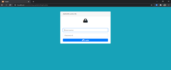
Figure 16. Login Form This form showed the login form for admin consist of username and password.
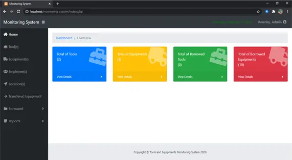
Figure 17.Home this form showed the main menu of the system where the user could select what process they want to open.
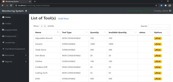
Figure 18. List of Tools this form showed the list of tools in the system where the user could add new tools and update.
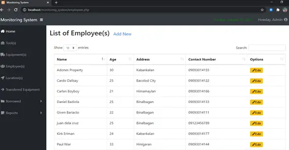
Figure 19. List of Equipment This form showed the list of Equipment’s in the system where the user could add new equipment and update.
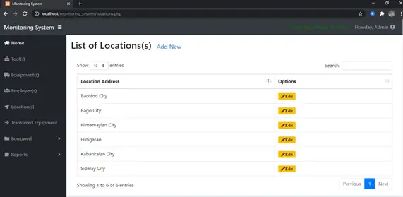
Figure 20. List of Employees this form showed the list of Employees in the system where the user could add new employees and update.

Figure 21. List of Location This form showed the list of locations in the system where the user could add new locations site and update.
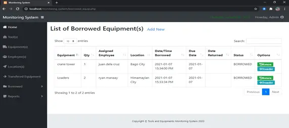
Figure 22. List of Borrowed Equipment’s this form showed the list of equipment’s in the system where the user could add new borrowed equipment and update its either it is returned or transferred.
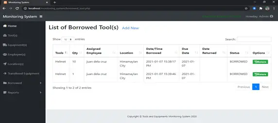
Figure 23. List of Borrowed Tools This form showed the list of borrowed tools in the system where the user could add new borrowed tools and update.
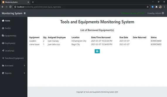
Figure 24. Reports this form showed the records of borrowed tools and equipment in the system where the user could print all the reports.
Project for Tools and Equipment Monitoring System – Gantt Chart
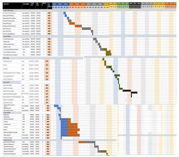
Figure 25: Tools and Equipment Monitoring System gantt chart.
Operational Framework
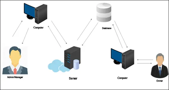
Figure 26: Tools and Equipment Monitoring System Operational Framework.
Figure 26 shows the operational Framework of Tools and
Equipment Monitoring System. The system components include the admin/manager, computer, server, database, owner.
Hardware and Software Used for Developing the System
In the development of the system, the developer uses both software and hardware are recommended.
Hardware Specification
Processor: Intel4Core N4200, 2.5GHz
Installed memory (RAM): 4.00GB (3.83 GB usable)
OS: Windows 10
System type: 64-bit Operating System, x64-based processor
Others:
Mouse
Barcode Scanner
Software
MYSQL (php my admin)
XAMPP Control Panel
SUBLIME TEXT 3
Related Capstone Resources
- Tools And Equipment Monitoring System Results
- Tools And Equipment Monitoring System Chapter 1
- Tools And Equipment Monitoring System Documentation Chapter 2
- Tools And Equipment Monitoring System Project
- Automated Basketball Scheduling And Monitoring System Methodology
- Chapter 3 Methodology Attendance Monitoring System 2019 Doc
Inquiries
If you have any questions or suggestions about Project for Tools and Equipment Monitoring System, please let me know by dropping your comment below.
Official references
Frequently asked questions
How many pages should a BSIT capstone chapter be?
Chapter 1 (Introduction) is typically 8-12 pages. Chapter 2 (RRL) is 15-25 pages. Chapter 3 (Methodology and System Design) is 15-30 pages depending on diagram count. Chapter 4 (Results) is 10-20 pages. Chapter 5 (Conclusions) is 5-10 pages. Total: 60-100 pages for the whole capstone.
What order should I write the chapters in?
Recommended order: Chapter 3 first (system design and methodology — most concrete), then Chapter 1 (introduction with the problem statement), then Chapter 2 (RRL to justify Chapter 1), then Chapter 4 (results — after implementation), then Chapter 5 (conclusions). This avoids rewrites and speeds up defense readiness.
What formatting style should I use for the capstone documentation?
Most Philippine BSIT programs require IEEE or APA 7th edition. Confirm with your adviser first. Use Times New Roman 12pt, double-spaced, 1-inch margins, and page numbers. Reference all sources properly and use consistent citation style throughout.
How many references do I need per chapter?
Chapter 1: 5-10 references. Chapter 2 (RRL): 20-40 references. Chapter 3: 10-15 references. Chapter 4-5: minimal, mostly self-referential. Recent sources (last 5 years) are strongly preferred over older ones.
What tools help write the capstone chapters?
Zotero or Mendeley for reference management, Grammarly for language check, Turnitin for plagiarism scan, Google Docs for collaboration with adviser, LaTeX (Overleaf) for advanced formatting, and ChatGPT or Claude for outline scaffolding (not for writing the actual content).

Adrian Mercurio
Full-Stack Developer at PIES IT Solution
Specializes in building complete capstone projects with full documentation. Strong background in PHP/MySQL development and database design. Has personally built and tested over 30 capstone-ready projects with ER diagrams, DFDs, and chapter-by-chapter thesis documentation.
Expertise: PHP, Laravel, Database Design, Capstone Projects, C#, C, C++, Python, AI Projects · View all posts by Adrian Mercurio →