
University Management System UML Diagrams
University Management System UML Diagrams – are diagrams formed to design the structure and behavior of the project. These UML Diagrams were used to visualize the possible users, processes, activities, and sequence of events in the University Management System. Its purpose is to analyze, understand and know the needs of the project before developing it.
Table of contents
Project Name and Tools Used
The table shows the overview of University Management System UML Diagrams. It tells the content of the article and the tools used to create UML Diagrams.
| Name: | University Management System |
| Abstract: | The UML Diagrams are part of project documentation that represents the overall University Management System function. Each of these diagrams shows different visualization of University Management System structures and behavior. |
| UML Diagrams: | Class Diagram, Use Case Diagram, Sequence Diagram, and Activity Diagram. |
| Other Diagrams: | ER Diagram and DFD (Data Flow Diagram) |
| Tools used: | Lucidchart.com was used to create the diagrams but you may use other diagram tools. |
UML diagrams are based on the UML (Unified Modeling Language) used to describe the University Management System. It includes the. major actors, roles, actions, artifacts, or classes, to better understand, edit, maintain, or document information.
Software engineers use the UML modeling language to create diagrams. That is to provide ready-to-use, expressive modeling examples to users (programmers). The UML Diagrams are categorized into two types: the structural diagrams and the behavioral diagrams.
The Structural UML Diagrams represent the rightful structure and features of the University Management System. On the other hand, the Behavioral UML Diagrams illustrate the System’s behavior towards the users and data handling.
The UML Diagrams are part of project documentation that represents the overall University Management System. Each of these diagrams shows different visualization of University Management System structures and behavior. That is to know how the system’s data handling and interaction with the targeted users.
The answer is YES. Its because the UML diagrams are the visual designs or the blueprint of the system’s structure and behavior. Structural diagrams help in building the structure of the University Management System while the behavioral diagrams in UML help in determining its behavior towards the user, data inputs, and producing an output. All of the UML diagrams work in sync and relatively to achieve a well-engineered project.
How to build UML Diagrams?
Time needed: 5 minutes
The UML Diagram development steps and guidelines are provided here. You don’t have to burden yourselves because each of these steps was also applied in the UML diagrams developed.
- Step 1: Gather Information
The first thing that you must do before building UML Diagrams for the system is to collect as much university management data as you can. You’ll need to know how they manage students’ information and process school-related transactions.
You must complete all the necessary information to provide quality software for them. Then you’ll apply the data gathered in designing the UML diagrams. - Step 2: Evaluate
After gathering much information, you will have to evaluate them. You will only include the important processes done in university management. The targeted users can help you in evaluating the needed processes and you will then convert them into modules or features.
- Step 3: Start creating your Blueprint.
The blueprints stand for the diagrams that you’ll create. The information gathered and evaluated will be the important basis for creating it.
You will start segregating all the data according to the entities that needed to be emphasized. Examples of which are:
• Class Diagram – focuses on data structures.
• Use Case Diagram – focuses on processes.
• Sequence Diagram – focuses on sequences of events.
• Activity Diagram – focuses on users’ activities or interactions with the system.
University Management System Project UML Diagrams
The purpose of building the system is to provide the university Staff and Admin with an easier and more efficient way of doing their task. And to do that, you have to complete the needed diagrams to perfectly furnish your project. Build your project completely using UML Diagrams to help you and keep you from errors during the development.
Here are the UML Diagrams that compose a University Management System. Each of the UML Diagrams has a major role in achieving a well-developed and functional University Management System. They were provided with an explanation of how each of the diagrams was created.
Class Diagram
The Class diagram for University Management System shows the structures of information or data that will be handled in the project. These data or information will be represented by classes. Each of the classes will have its attributes in accord with the methods they will use. So the UML Class diagram was illustrated by a box with 3 partitions the upper part was the name of the class, the middles are the attributes and the bottom is for the methods. The arrows on them represent their relationships with each other.
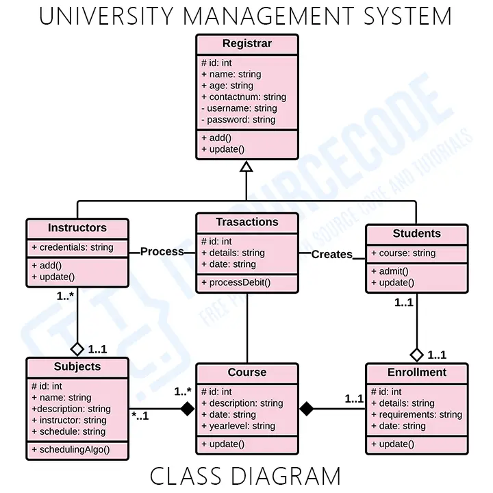
So the classes that are included in University Management would be the students, enrollment, instructors, subjects, courses, registrar, and transaction. The mentioned classes were just general. If you want a more complex or wider scope of your University management system, then you can add your desired classes. You must also include the database on your Class Diagram for your system.
Use Case Diagram
The use cases in the diagram represent the main processes in University Management System. Then they will be broken down into more specific use cases depending on the included processes of the main use case. Each of these use cases explains how the system handles the actions or scenarios requested by the user.
The general use case is the most common application of a use case diagram. The use case diagrams depict the system’s main components as well as the flow of information between them.
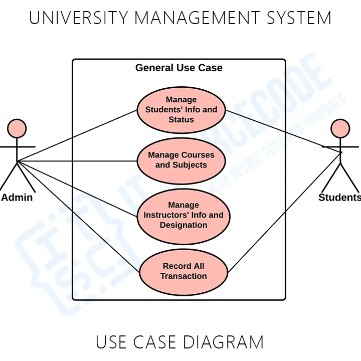
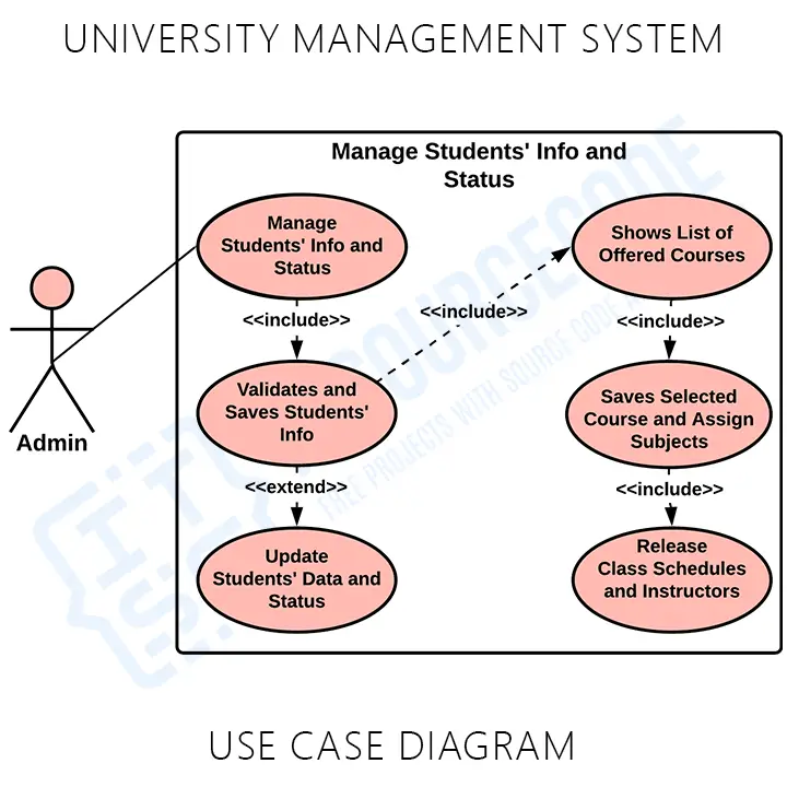
Monitor and Manage Students’ Information and Status – This is where the university admin manages the important information of the students that will serve as a basis during a student process a transaction and update their status.
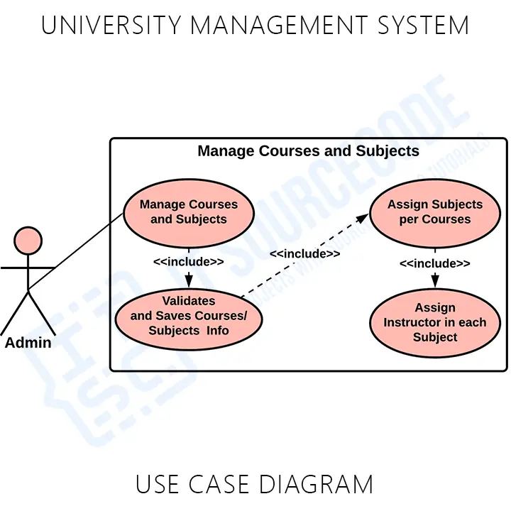
Manage Courses Department and Subjects – Its process includes the managing of the courses’ and subjects’ information that is offered by the university. These processes were important to the system because its the basis for the student’s status update and what are the subjects to be taken based on the course they have taken.
Manage Instructors’ Information and Designation – This is the process where the admin will gather the instructors’ information and will manage their requirement for teaching and assign them to the subjects that suits their qualifications.
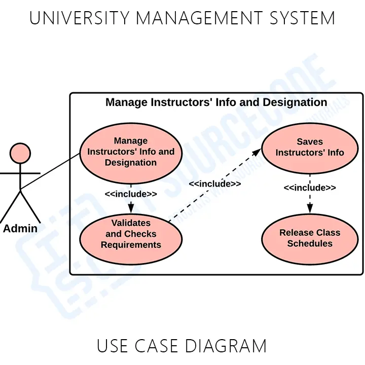
The UML Use Case Diagram is a design used as one of the Methodologies for University Management System development. It represents the main functions or processes of the system as well as the specific processes included. They were also labeled properly to guide programmers and users about the structure of the University Management System.
Sequence Diagram
The designed sequence diagram illustrates the series of events that occurs in the University Management System. In this illustration, the actors are represented by a stick man, and the transactions or classes are represented by objects. It will give you a clear explanation of the behavior of a University Management System in terms of processing the flow of instructions.
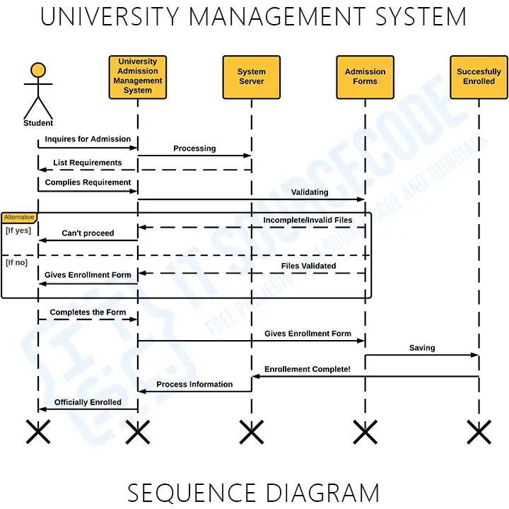
This designed sequence diagram can show programmers and readers the sequence of messages between the actor and the objects.
Activity Diagram
Here’s the UML activity diagram design of the University Management System that you can use for your own Final year Project. The UML activity diagram is used to show the interaction between the user and the system. By creating it, you’ll be able to see the flaws of the system and you may avoid them once you apply them to the project development. So it is important to have your diagrams designed first before jumping into its development.
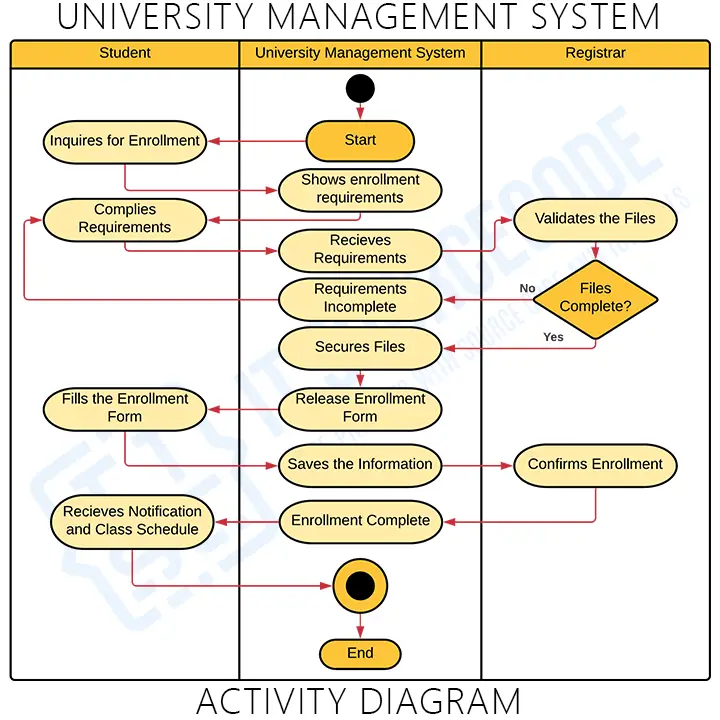
Now to create this kind of diagram, you have to determine the processes involved, and the users and finalize the behavior of your proposed system.
Bonus Diagrams
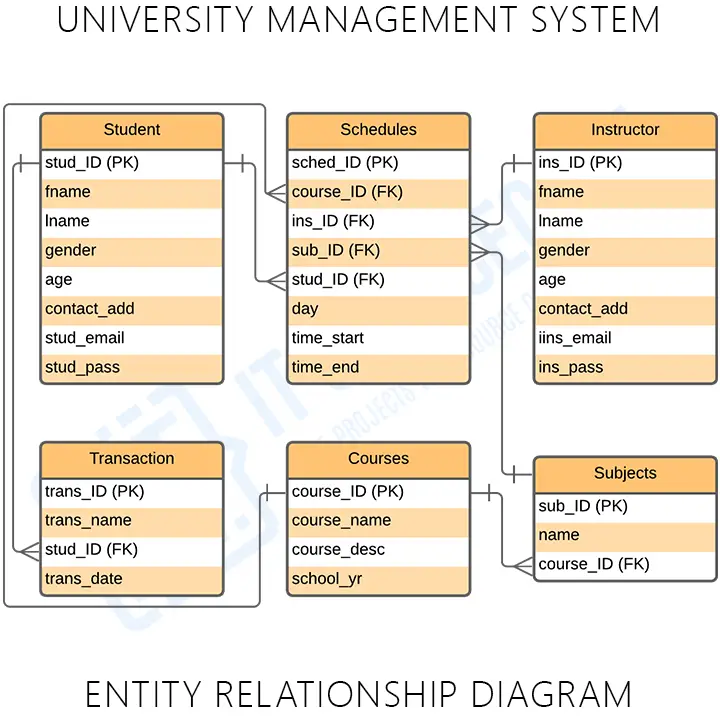
- University Management System ER Diagram
This diagram shows the design of the system’s database. This design could be applied at the back end of the system development. It also serves as the design for the data storage that the system needs. It secures all the essential data in the system and preserves them for an important task or when needed.
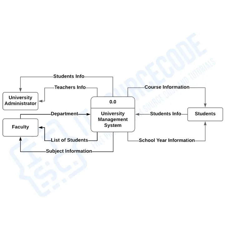
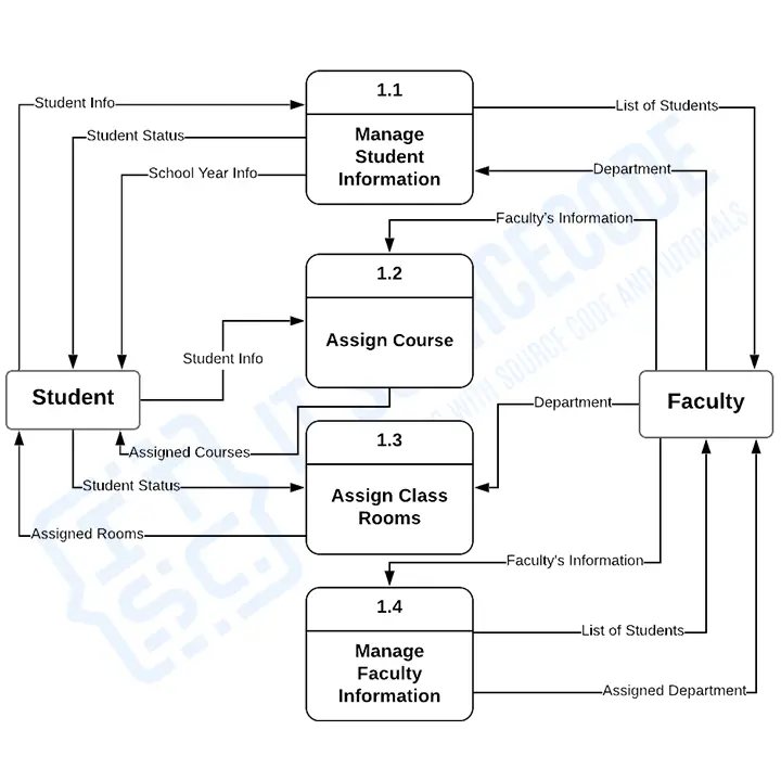
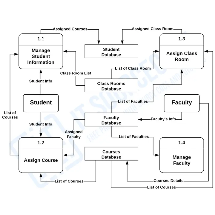
- University Management System DFD
In an addition to the diagrams that will be a big help in doing your Project is the Data Flow Diagram. It does not belong to the UML diagrams but it also helps in knowing more about the University Management System. So the DFD serves as an illustration of the systems data handling. It has levels 0, 1, and 2.
Bonus Tips
To design your UML diagrams, you may use platforms and editing tools online. These tools are helpful since they already have the needed symbols to illustrate your diagrams. You just have to plot the included symbols, arrows, and labels. The platforms or online tools that you may use are:
• Lucidchart
• Creately
• Smartdraw
• Edrawmax
• Canva
Conclusion:
As a whole, the UML Diagrams work together to achieve the most desired functions of the University Management System Project. All of these were designed to guide programmers and beginners about the behavior and structure of the University Management System.
By completing all the given Diagrams, the University Management System development would be much easier and more attainable. So those UML diagrams were given to teach you and guide you through your project development journey. You can use all of the given UML diagrams as your reference, or have them for your project development. The ideas presented in UML Diagrams were all based on University Management System requirements.
Related Articles:
- Point of Sale (POS) System UML Diagrams
- Bank Management System UML Diagrams
- Restaurant Management System UML Diagrams
- School Management System Project UML Diagrams
- College Management System Project UML Diagrams
- Blood Bank Management System UML Diagrams
Recommended Articles:
- University Management System In PHP FREE Download
- Online University Management System Project Report & Documentation
- University Residence Booking System in Django with Source Code
Inquiries:
Now let me ask you something. What have you learned through the discussion? May this article help you with your projects in the future!
If you have inquiries or suggestions about University Management System Complete UML Diagrams just leave us your comments below.
Keep us updated and Good day!