Data Flow Diagram Examples (Level 0, 1, 2) – This article will give you an idea about Data Flow Diagram (Level 0, 1, 2) Examples In Software Engineering 2023.
This will cover some about what is a Data Flow Diagram and how to create one.
Most of the data flow diagram examples below are designed for students who are currently taking up a computer-related course and are doing their final-year projects.
What is a Data Flow Diagram?
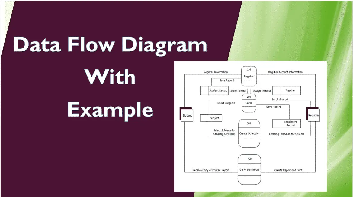
A Data Flow Diagram (DFD) is a way of visual representation of a flow of data in a certain process or system.
The data flow diagram can provide information about the process, inputs, and outputs of each entity.
The data flow diagram uses defined symbols like rectangles, circles, and arrows, plus short text labels, to show data inputs, outputs, storage points, and the routes between each destination.
📌Reminder
A data flow diagram has no decision, loops, or control flow.
Data Flow Diagram Examples (Level 0, 1, 2 ) in Software Engineering 2023 (Free Template)
Here is the list of data flow diagram examples (level 0, 1, 2) in Software Engineering.
Dataflow Diagram levels 0 1 2 for Library Management System
DFD for Library Management System Level 0 ✅
To start with, let us familiarize ourselves is library management system level 0.
The Library Management System level 0 is also known as the context diagram. It’s supposed to be an abstract view, with the mechanism represented as a single process with external parties.
This DFD for the library management system depicts the overall structure as a single bubble. It comes with incoming/outgoing indicators showing input and output data.
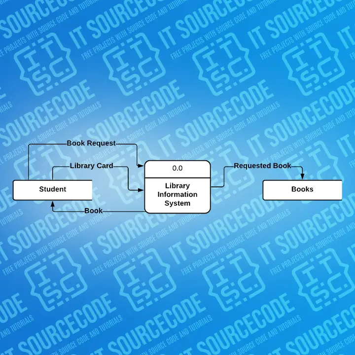
In this data flow diagram, you will see the general process done in library management.
This will also serve as a guide as you go through the deeper processes of the library management system data flow diagram examples in software engineering.
As you see, when you build the levels of data flow diagrams, the connections of the transactions and data also broaden and gets more specific.
DFD for Library Management System Level 1 ✅
Next to the context diagram is the level 1 data flow diagram.
The content of library management system level 1 must be a single process node from the context diagram is broken down into sub-processes
At this level, the device must display or reveal further processing information.
The following are critical procedures to complete:
• Make a Book Request
• Topic-based search
These procedures require information such as a list of authors, titles, topics, and bookshelves from which books can be located. This type of data is represented by a data store.
With being knowledgeable about the second level of the Library Management System DFD, you will know its breakdown processes.
In addition to that, this may also serve as your reference on how the inputs or data fed on the system. Then you will be informed about the outputs that the system gives.
These processes shown in the DFD were all based on the concept of a Library Management System.
DFD for Library Management System Level 2 ✅
After presenting the library management system DFD levels 0 and 1, next to that is level 2.
Here’s what you need to consider in creating a data flow diagram level 2 for the library management system.
• The Level 2 DFD for the library management system should represent the basic modules as well as the data flow between them.
• Since the DFD level 2 is the highest abstraction level, its library management system processes must be detailed that is based on the DFD level 1.
Finally, after figuring out the processes given in the system, the user will now have their request processed.
At this level, you will now have ideas about where the data inputs go and where inputs come.
Considering the dataflow levels mentioned above, you can determine well the importance of breaking the processes into a more specific manner.
The presented level not only shows you the detailed processes of the Library management system but also gives you the precise destination of the data that flows in the system.
This figure will also be your reference as you make your own projects.
(Note: In the image below is only level 0 of a library management system. To see the complete Level, click the above link.)
Hospital Management System DFD Level 0, 1, 2
DFD for Hospital Management System Level 0 ✅
To start with, let us familiarize ourselves what is Hospital management system Level 0.
The hospital management system level 0 is also known as the context diagram. It’s supposed to be an abstract view, with the mechanism represented as a single process with external parties.
This DFD for the system depicts the overall structure as a single bubble. It comes with incoming/outgoing indicators showing input and output data.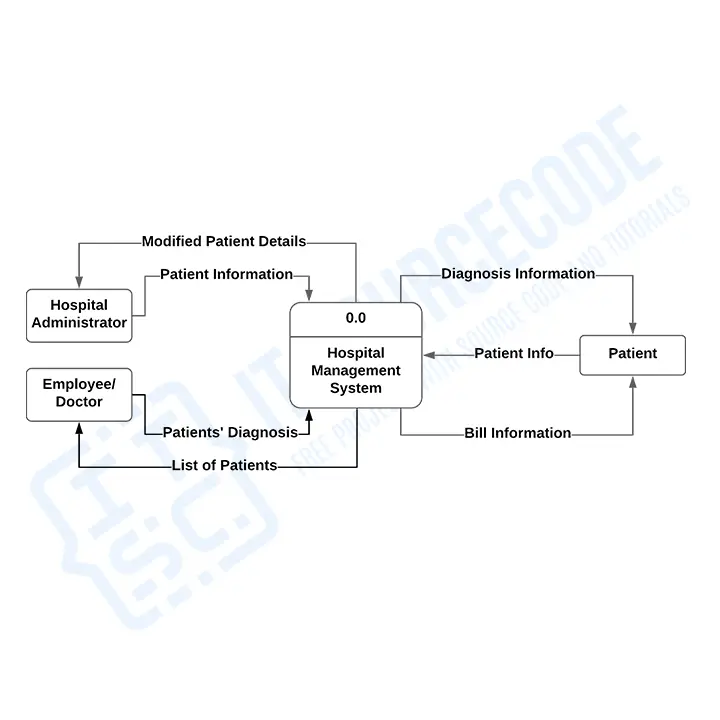
In this data flow diagram, you will see the general process done in Hospital management.
This will also serve as a guide as you go through the deeper processes of the Hospital management system data flow diagrams.
As you see, when you build the levels of data flow diagrams, the connections of the transactions and data also broaden and get more specific.
DFD for Hospital Management System Level 1 ✅
Next to the context diagram is the level 1 data flow diagram.
The content of the Hospital management system DFD level 1 must be a single process node from the context diagram and is broken down into sub-processes
At this level, the system must display or reveal further processing information. The actors that are going to use this system are the patients, the hospital administrators, and the hospital employees.
The following are essential data to accommodate:
• Patient Information
• Employees Information
• Medicines
• Facilities
These procedures require information such as a list of patients, medicines, employees/doctors, and facilities which served as the basis for admin to manage hospital transactions. This type of data is represented by a data store.
With being knowledgeable about the DFD level 1 of the Hospital Management System, you will know then its broaden context terms.
In addition to that, this may also serve as your reference on how the inputs or data are fed into the system. Then you will be informed about the outputs that the system gives.
These processes shown in the DFD were all based on the concept of a Hospital Management System.
DFD for Hospital Management System Level 2 ✅
After presenting the Hospital management system DFD levels 0 and 1, next to that is level 2.
Here’s what you need to consider in creating a data flow diagram level 2 for the Hospital management system.
• The Level 2 DFD for the system should represent the basic modules as well as the data flow between them.
• Since the DFD level 2 is the highest abstraction level, its Hospital management system processes must be detailed and based on the DFD level 1.
Finally, after figuring out the processes given in the system, the user will now have their request processed.
The Processes that the system should prioritize are as follows:
• Managing Patient
• Assigning Medicine
• Managing Employees/Doctors
• Assigning Facilities
DFD level 2 lets you know the ideas on where the data inputs go and how inputs come within the Hospital management system.
Considering the dataflow levels mentioned above, you can determine well the importance of breaking the processes into a more specific manner.
The presented level not only shows you the detailed processes of the system but also gives you the precise destination of the data that flows in the system.
This DFD will also be your reference as you make your own management system DFD levels 0, 1, and 2.
(Note: In the image below is only the level 0 of a hospital management system. To see the complete Level, click the above link.)
Student Management System DFD Level 0 1 2
DFD for Student Management System Level 0 ✅
The system level 0 is also known as the context diagram. It’s supposed to be an abstract view, with the mechanism represented as a single process with external parties.
This DFD depicts the overall structure as a single bubble. It comes with incoming/outgoing indicators showing input and output data.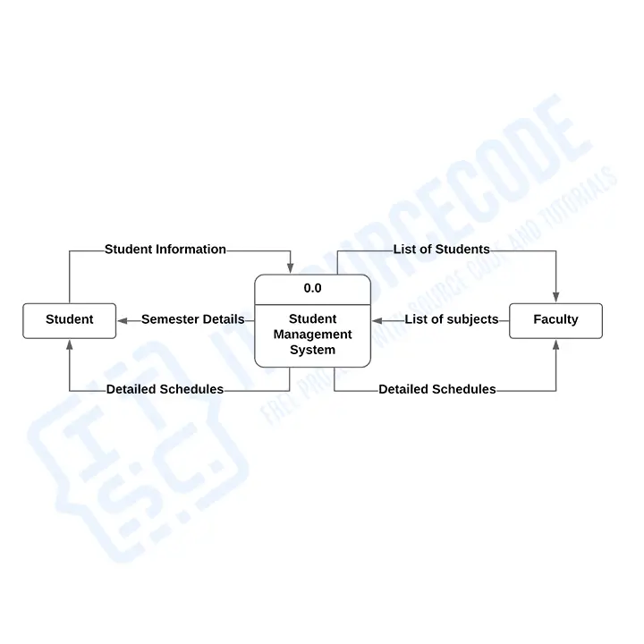
In this data flow diagram, you will see the general process done in student management data flow diagram examples in software engineering.
This will also serve as a guide as you go through the deeper processes of the student management system data flow diagrams.
The content of Student Management System level 1 must be a single process node from the context diagram is broken down into sub-processes
DFD for Student Management System Level 1 ✅
Next to the context diagram is the level 1 data flow diagram.
The content of Student Management System level 1 must be a single process node from the context diagram is broken down into sub-processes
At this level, the system must display or reveal further processing information. And the actors that are going to use this system are the students and the faculty.
The following are essential data to accommodate:
• Schedules
• Subjects
• Attendance
• Semesters
These procedures require information such as a list of students, subjects, attendance, and semesters which served as the basis for faculty to manage students. This type of data is represented by a data store.
With being knowledgeable about the DFD level 1, you will know then its broaden context terms.
In addition to that, this may also serve as your reference on how the inputs or data are fed into the system. Then you will be informed about the outputs that the system gives.
These processes shown in the DFD were all based on the concept of the Student Management System.
Here’s what you need to consider in creating a data flow diagram level 2 for the student management system.
DFD for Student Management System Level 2 ✅
After presenting the student management system DFD levels 0 and 1, next to that is level 2.
• The Level 2 DFD for the student management system should represent the basic modules as well as the data flow between them.
• Since the DFD level 2 is the highest abstraction level, its student management system processes must be detailed and based on the DFD level 1.
Finally, after figuring out the processes given in the system, the user will now have their request processed.
The Processes that the system should prioritize are as follows:
• Assigning of Attendance
• Assigning of Schedules
• Plotting of Subjects
DFD level 2 lets us know the ideas on where the data inputs go and inputs come within the student management system.
Considering the data flow mentioned above, you can determine well the importance of breaking the processes into a more specific manner.
The presented level not only shows you the detailed processes of the system but also gives you the precise destination of the data that flows in the system.
This DFD will also be your reference as you make your own student management system DFD levels 0, 1, and 2.
(Note: In the image below is only the level 0 of a Student Management System DFD Level 0 1 2. To see the complete Level, click the above link.)
College Management System DFD Level 0 1 2
DFD for College Management System Level 0 ✅
To start with, let us familiarize ourselves what is College Management System Level 0.
The College management system level 0 is also known as the context diagram. It’s supposed to be an abstract view, with the mechanism represented as a single process with external parties.
This DFD for the college management system depicts the overall structure as a single bubble. It comes with incoming/outgoing indicators showing input and output data.
In this data flow diagram, you will see the general process done in College management. This will also serve as a guide as you go through the deeper processes of the management system data flow diagrams.
As you see, when you build the levels of data flow diagrams, the connections of the transactions and data also broadens and get more specific.
DFD for College Management System Level 1✅
Next to the college management system context diagram is the level 1 data flow diagram.
The content of the College management system DFD level 1 must be a single process node from the context diagram and is broken down into sub-processes.
At this level, the system must display or reveal further processing information. And the actors that are going to use this system are the college students and college administrators.
The following are essential data to accommodate:
• Student Information
• Teacher’s Information
• Class Rooms
• College Facilities
These procedures require information such as a list of College Students, classrooms, teachers, and facilities which served as the basis for admin to manage college transactions. This type of data is represented by a data store.
With being knowledgeable about the DFD level 1 of the College Management System, you will know then its broaden context terms.
In addition to that, this may also serve as your reference on how the inputs data on the college management system. Then you will be informed about the outputs that the system gives.
These processes shown in the DFD were all based on the concept of a College Management System.
DFD for College Management System Level 2 ✅
After presenting the College management system DFD levels 0 and 1, next to that is level 2.
Here’s what you need to consider in creating a data flow diagram level 2 for the College management system.
• The Level 2 DFD for the college management system should represent the basic modules as well as the data flow between them.
• Since the DFD level 2 is the highest abstraction level, its processes must be detailed that is based on the DFD level 1.
Finally, after figuring out the processes given in the system, the user will now have their request processed.
The Processes that the system should prioritize are as follows:
• Managing Student Information
• Assigning Class Rooms
• Managing Teachers
• Assigning Course
• Setting Timetables
DFD level 2 lets you know the ideas on where the data inputs go and inputs come within the College management system.
Considering the dataflow levels mentioned above, you can determine well the importance of breaking the processes into a more specific manner.
The presented level not only shows you the detailed processes of the system but also gives you the precise destination of the data that flows in the system.
This DFD will also be your reference as you make your own management system DFD levels 0, 1, and 2.
(Note: In the image below is only the level 0 of a College Management System DFD Level 0 1 2. To see the complete Level, click the above link.)
Hotel Management System DFD Level 0 1 2
DFD for Hotel Management System Level 0 ✅
To start with, let us familiarize ourselves what is Hotel Management System Level 0.
The hotel management system level 0 is also known as the context diagram. It’s supposed to be an abstract view, with the mechanism represented as a single process with external parties.
This DFD for the system depicts the overall structure as a single bubble. It comes with incoming/outgoing indicators showing input and output data.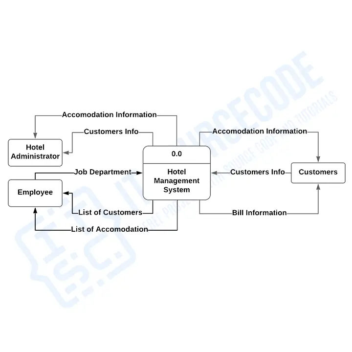
In this data flow diagram, you will see the general process done in Hotel management. This will also serve as a guide as you go through the deeper processes of the Hotel management system data flow diagrams.
As you see, when you build the levels of data flow diagram examples in software engineering, the connections of the transactions and data also broaden and get more specific.
DFD for Hotel Management System Level 1 ✅
Next to the context diagram is the level 1 data flow diagram.
The content of the Hotel management system DFD level 1 must be a single process node from the context diagram and is broken down into sub-processes
At this level, the system must display or reveal further processing information. And the actors that are going to use this system are the customers, the hotel administrator, and the hotel employees.
The following are essential data to accommodate:
• Customer Information
• Employees Information
• Rooms
• Reservation
These procedures require information such as a list of customers, rooms, employees, and facilities which served as the basis for admin to manage hotel transactions. This type of data is represented by a data store.
With being knowledgeable about the DFD level 1 of the Hotel Management System, you will know its broader context terms.
In addition to that, this may also serve as your reference on how to input data into the system.
Then you will be informed about the outputs that the system gives.
These processes shown in the DFD were all based on the concept of a Hotel Management System.
DFD for Hotel Management System Level 2 ✅
After presenting the Hotel management system DFD levels 0 and 1, next to that is level 2.
Here’s what you need to consider in creating a data flow diagram level 2 for the Hotel management system.
• The Level 2 DFD for the system should represent the basic modules as well as the data flow between them.
• Since the DFD level 2 is the highest abstraction level, its Hotel management system processes must be detailed and based on the DFD level 1.
Finally, after figuring out the processes given in the system, the user will now have their request processed.
The Processes that the system should prioritize are as follows:
• Managing Clients
• Assigning Rooms
• Managing Employees
• Facilitates Reservation
• Manage Transactions
DFD level 2 lets us know the ideas on where the data inputs go and what inputs come within the Hotel management system.
Considering the dataflow levels mentioned above, you can determine well the importance of breaking the processes into a more specific manner.
The presented level not only shows you the detailed processes of the system but also gives you the precise destination of the data that flows in the system.
This DFD will also be your reference as you make your own management system DFD levels 0, 1, and 2.
(Note: In the image below is only the level 0 of a Hotel Management System DFD Level 0 1 2. To see the complete Level, click the above link.)
University Management System DFD Level 0 1 2
University management system level 0 ✅
To start with, let us familiarize ourselves what is the University management system level 0.
The University management system level 0 is also known as the context diagram. It’s supposed to be an abstract view, with the mechanism represented as a single process with external parties.
In this data flow diagram, you will see the general process done in university management. This will also serve as a guide as you go through the deeper processes of the management system data flow diagrams.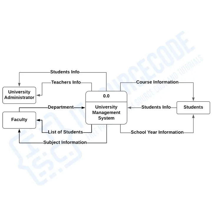
This university management system data flow diagram examples in software engineering depict the overall structure as a single bubble.
It comes with incoming/outgoing indicators showing input and output data.
As you see, when you build the levels of data flow diagrams, the connections of the transactions and data also broaden and get more specific.
DFD for University Management System Level 1 ✅
Next to the university management system context diagram is the level 1 data flow diagram.
The content of the University management system DFD level 1 must be a single process node from the context diagram and is broken down into sub-processes.
At this level, the system must display or reveal further processing information. And the actors that are going to use this system are the students and university administrators.
The following are essential data to accommodate:
• Student Information
• Faculty’s Information
• Class Rooms
• University Facilities
These procedures require information such as a list of Students, classrooms, faculty, and facilities from which served as the bases for admin to manage university transactions. This type of data is represented by a data store.
With being knowledgeable about the DFD level 1 of the University Management System, you will know its broader context terms.
In addition to that, this may also serve as your reference on how the inputs or data are fed into the university management system. Then you will be informed about the outputs that the system gives.
These processes shown in the Data Flow Diagram were all based on the concept of the University Management System.
DFD for University Management System Level 2 ✅
After presenting the University management system DFD levels 0 and 1, and next to that is level 2.
Here’s what you need to consider in creating a data flow diagram level 2 for the University management system.
• The university management system Level 2 DFD should represent the basic modules as well as the data flow between them.
• Since the DFD level 2 is the highest abstraction level, its processes must be detailed that is based on the DFD level 1.
Finally, after figuring out the processes given in the system, the user will now have their request processed.
The Processes that the system should prioritize are as follows:
• Managing Student Information
• Assigning Class Rooms
• Managing Faculty’s Information
• Assigning Courses
• Setting School Year
Data flow diagram example level 2 lets you know the ideas on where the data inputs go and inputs come within the university management system.
Considering the dataflow levels mentioned above, you can determine well the importance of breaking the processes into a more specific manner.
The presented level not only shows you the detailed processes of the system but also gives you the precise destination of the data that flows in the system.
This data flow diagram example will also be your reference as you make your own university management system DFD levels 0, 1, and 2.
(Note: In the image below is only the level 0 of a Hotel Management System DFD Level 0 1 2. To see the complete Level, click the above link.)
Conclusion
This data flow diagram level 0, 1, 2 examples is designed for student final year projects and you can copy and modify this to suit your needs especially if you are doing your thesis Document and don’t know where and how to start.
Recommended Articles
- Writing A Good Research Title For a Thesis or Capstone Project
- How to Write Chapter 1 Research Description Capstone
- list of Best Thesis Title proposal for IT
- Best project Topics for Computer Science Students
But if you are looking for a complete system, you can check here List of VB.NET Projects with Source Code to support your system documentation.
Inquiries
If you have any questions or suggestions about this data flow diagram level 0, 1, or 2 examples, please feel free to leave a comment below.
Why Level 1 diagram is not given