In this article, I will show you how to connect a potentiometer to Arduino by controlling an LED.
A potentiometer is simply a varying resistor. This means you can amplify or reduce the amount of electricity passing through the circuit.
Today, I will show you the ropes in wiring a potentiometer to integrate in your next project.
Connecting a Potentiometer to Arduino: Steps in Creating the Device
Here are the steps in creating RFID Door Lock Arduino Project with Data Logging in Python.
- Gathering the Components
The first thing to do is to collect the hardware components for the Arduino device.
Arduino Uno
Potentiometer
LED - Connecting the Components
Connect the components to the Arduino Uno. Please refer to the wiring diagram below.
- Coding the Arduino
Third step is about coding the Arduino device.
- Upload the Sketch
Final step is uploading the sketch to the Arduino.
Step 1: Gathering the Components
To start off, this project will have two parts: the Arduino Device and the Program. First thing to do is to collect the hardware components and make the device. To do that, you will be needing the following:
| Quantity | Components |
| 1 | Arduino Uno |
| 1 | Potentiometer |
| 1 | LED |
Arduino UNO
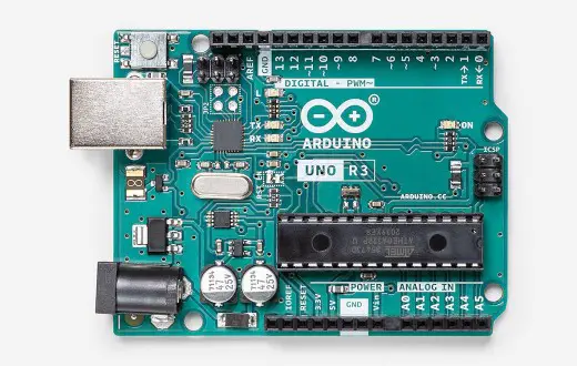
You will be using Arduino Uno for this project. It is an easy to use microprocessor board. Arduino Uno is suitable for any projects and is the cheapest and widely used microprocessor board in the Arduino family. This is great for all kinds of IoT projects.
Potentiometer
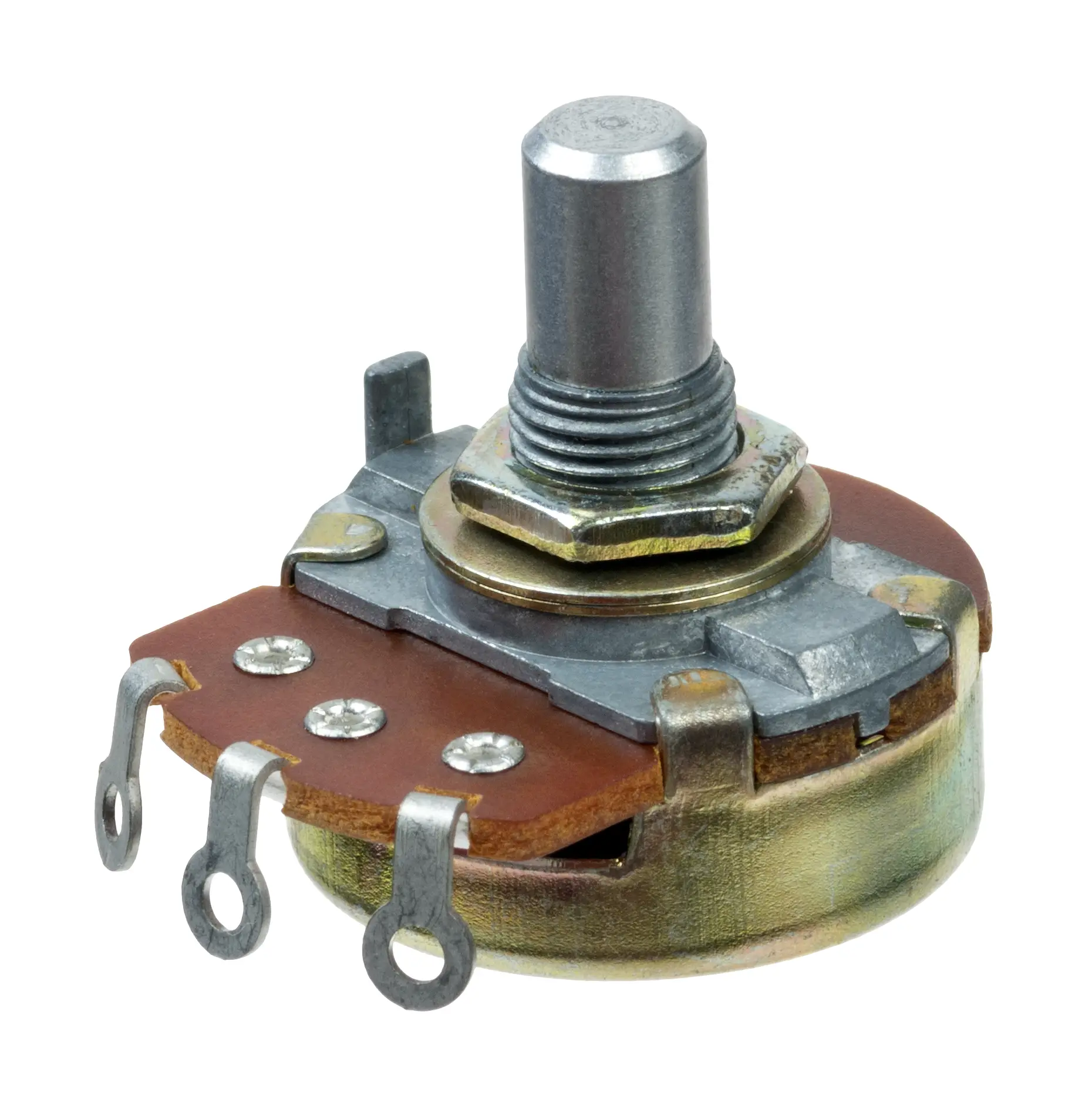
The image above is a potentiometer. It has 3 pins – VCC, the input pin for the Arduino, and the GND. Some type needs to be soldered while some you can easily use on the breadboard.
Take note, if you want to give more power by turning the knob to the right, attach the 5V wire to the third pin.
LED
We will use a LED to demonstrate the potentiometer’s capability. The LED’s brightness will be controlled using the potentiometer.
Other Components
Other components (but not required) is a resistor and a LCD. You can use a resistor for the LED and display the values on the LCD. Don’t worry if you don’t have an LCD or resistor because the project will work just fine without them.
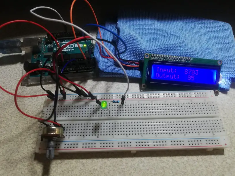
Step 2: Connecting the Arduino Components
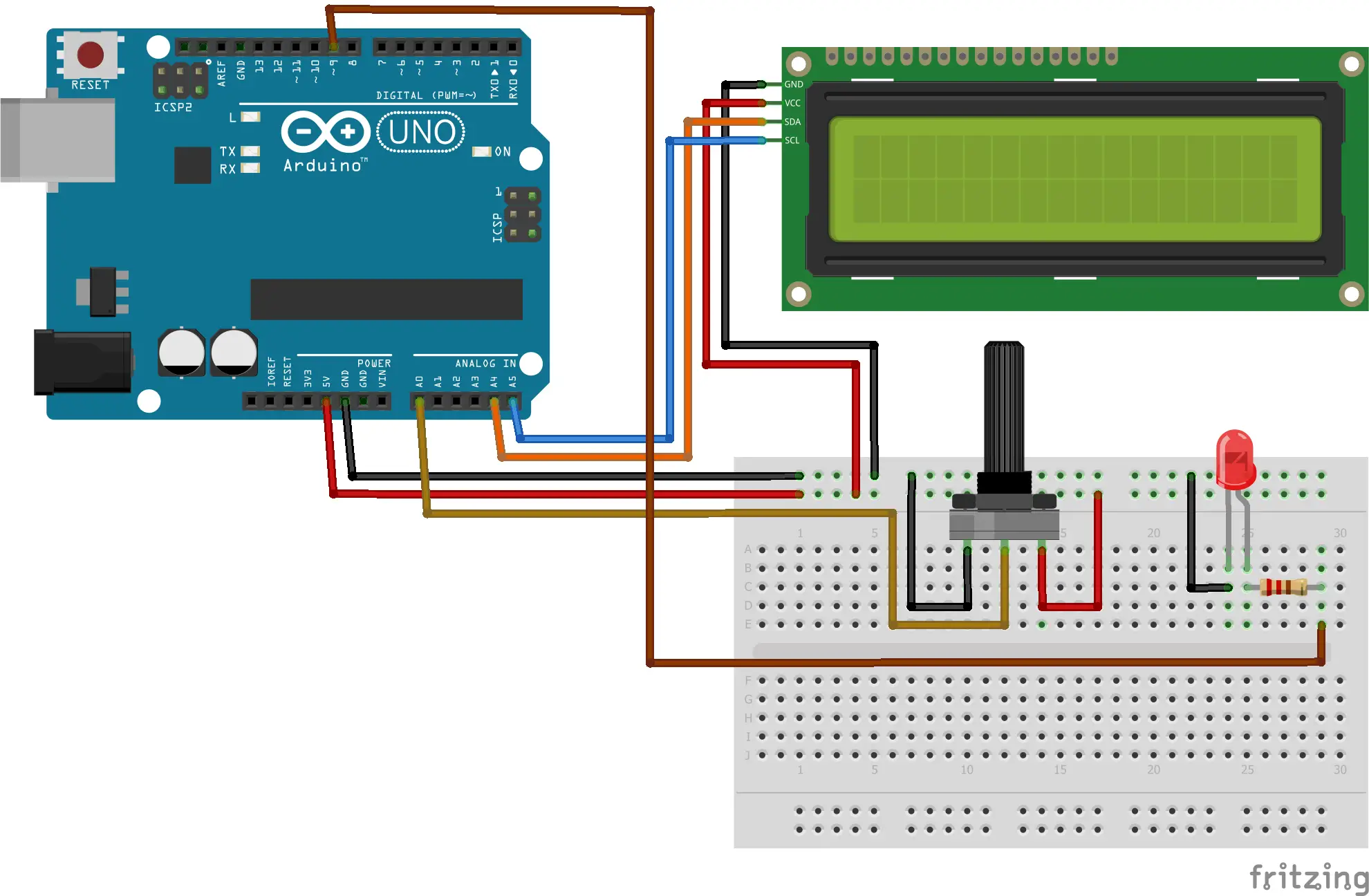
Now you are ready to connect the components to the Arduino Uno. Attach the middle pin of the potentiometer to the Analog Pin 0 of the Arduino and the longer leg of the LED to Digital Pin 9 or any Digital Pin that supports pulse-width modulation. This is indicated by a wavy dash beside the pin number.
Step 3: The Arduino Code
Now the wiring is done, all you need to do is copy the code and upload it to the Arduino. Simply remove the LCD codes if you don’t have any.
#include <LiquidCrystal_I2C.h>//Liquid Crystal Display with I2C
LiquidCrystal_I2C lcd(0x27, 16, 2);

const int analogPin = 0;//the analog input pin attach to

const int ledPin = 9;//the led attach to

int inputValue = 0;//variable to store the value coming from sensor

int outputValue = 0;//variable to store the output value


void setup()
{
 Serial.begin(9600);//set the serial
//communication baudrate as 9600
 lcd.init();   // LCD screen
 lcd.backlight();

}

void
 loop()
{

  inputValue = analogRead(analogPin);//read the value from the potentiometer
  lcd.setCursor(0,0);
  lcd.print("Input: "); //print "Input"
  lcd.setCursor(8,0);
  lcd.print(inputValue); //print inputValue

  outputValue = map(inputValue, 0, 1023, 0,
100); //Convert from 0-1023 proportional to the number of a number of from 0 to 100
  lcd.setCursor(0,1);
  lcd.print("Output: "); //print "Output"
  lcd.setCursor(9,1);
  lcd.print(outputValue); //print outputValue

  analogWrite(ledPin, outputValue); //turn the LED on depending on the output value
  delay(100);

}
Now upload the sketch to the Arduino.
Step 4: Test Run
After you successfully upload the sketch, turn the knob clockwise. The LED will slowly light up as the input increases.
Conclusion
So there you have it! Connecting a Potentiometer to Arduino. This project is intimidating at first but you will see that it is fairly easy to do. You can combine this to other Arduino projects and build an awesome system!
Download
Click the button below to download the source code.
Related Articles
Inquiries
Feel free to write your questions about this project at the comments below.