
Component Diagram for Bank Management System
The component diagram of bank management system is used to show how the parts work together to make the bank system operate correctly. A component diagram shows how the software’s parts are organized and how they depend on each other. This diagram gives a high-level look at the parts of a system.
Components of a bank management component diagram can be part of software or hardware. They could be a database, a user interface, or something else that helps the bank management system work.
Bank Management System Component Diagram: Table of contents
- Component Diagram for Bank Management System
- Component Diagram for Bank Management System: Details
- What is Bank Management System Description?
- What is Bank Management System Component Diagram in UML?
- The Component Diagram for bank Management System
- Bank Management System Component Diagram (Explanation)
- Bank Management System Component Diagram Pdf
- Characteristics of Component Diagram:
- Benefits of using Component Diagram
- Steps in Developing Component Diagram for Bank Management System
- Conclusion
- Related Articles:
- Recommended Articles from the Author:
- Inquiries
Component Diagram for Bank Management System: Details
The table shows the basic details of the component diagram of the bank system. It has quick description details of the component diagram illustration.
| Name: | Bank Management System Component Diagram |
| Abstract: | The bank management system UML component diagram is used in object-oriented programming to group classes together based on their common purpose. This way, the developer and others can see how a project is progressing at a high level. |
| UML Diagram: | Component Diagram |
| Users: | Bank Admin, Employee, and Bank Members. |
| Tools Used: | Diagraming Tools that have UML Component Diagram Symbols |
| Designer: | ITSourceCode.com |
What is Bank Management System Description?
The bank management system is a collection of software tools and processes used by banks to manage cash flows, client relationships, risk, and technology. Banks employ management systems for a variety of reasons, but they all share one purpose. They are responsible for ensuring that the bank manages itself to increase efficiencies and make better large-scale decisions.
The bank management system is used to keep track of clients, staff, and other information in the bank. It is a program that monitors a customer’s account in a bank. This allows the customer to create an account, deposit or withdraw money from the account, and examine reports for all accounts in the system. This guarantees that Real-Estate management duties run smoothly and that information about employees and their salaries is kept up to date.
It is the provision of financial services through the use of electronic communication and calculation. E-payment, e-shopping, and e-banking are all part of the online banking system. These statements were collected as the information concepts in developing the system UML diagrams. The concept formulated will be applied to the component diagram illustration.
What is Bank Management System Component Diagram in UML?
A component diagram in the (UML) Unified Modeling Language shows how parts are wired together to explain the parts of bank systems. They are used to show the structure of any kind of system.
The UML component diagram shows how a bank management system will be made up of a set of deployable components, such as dynamic-link library (DLL) files, executable files, or web services. Using well-defined interfaces, these parts communicate with each other and keep their internal details hidden from each other and the outside world.
The Component Diagram for bank Management System
This component diagram of bank management system is the illustration of the components of every hardware and software node. The component diagram below is a detailed illustration of the Deployment Diagram for Bank Management System.
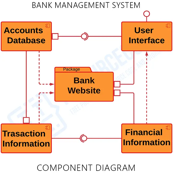
This component diagram shows the structure of the bank system, which consists of the software components and their interfaces, accounts database, transaction information, and financial information. Their dependencies explain how they work together. You can use component diagrams to show how software systems work at a high level, or you can use them to show how each component works at a lower level, like in a package.
Bank Management System Component Diagram (Explanation)
The Bank Management System UML component diagram explains the sketch of the required software and hardware components and the dependencies between them. These components are labeled to clarify their part in the system’s operation. They were represented by symbols that explain their function and role in the overall bank management system operation.
The component diagram of bank management system has 4 components and a package which are user interface, room management, reservation management, monitoring and updates, web interface, and the list of services. This diagram shows several interfaces that are provided and required. The client’s side package contains the required interfaces and the crew’s side contains the provided interfaces. The admin’s side package also holds and manipulates the crew’s components.
The dependencies on each component are explained through the lines and arrows drawn in the diagram.
Bank Management System Component Diagram Pdf
You may download the Component Diagram PDF by clicking the button below. It has the full details and discussion of the system’s component diagram. You can also modify its content to complete your project requirements and needs.
Characteristics of Component Diagram:
- In component-based development, they are used to describe systems that have a service-oriented architecture.
- Shows how the code itself looks.
- It can be used to focus on the relationship between the parts while hiding the specifics.
- Help stakeholders understand how the system being built works and how it will be used.
Benefits of using Component Diagram
As complicated as it looks, the component diagram is very important when you’re building your system because it shows how everything works together. Here are the benefits of designing the bank management system component diagram:
- Imagine how the system looks in real life.
- Pay attention to the system’s parts and how they work together.
- Pay attention to how the service behaves when it comes to the interface.
Steps in Developing Component Diagram for Bank Management System
Time needed: 10 minutes
Here are the steps in developing the bank management system component diagram.
- Finalize the Function and Processes of the Software
The first step in developing the component diagram is finalizing the processes and functions of the software. This activity will help programmers analyze what are the things needed to complete the bank management system process. Then the finalized processes or functions will be the base concept in designing the system’s component diagram.
- Put the Components included
A component is a piece of the system that makes sense in terms of logic. It’s a little more abstract than classes. There are tabs or the word “Component” written on top of the name of the component to help you tell it apart from a class.
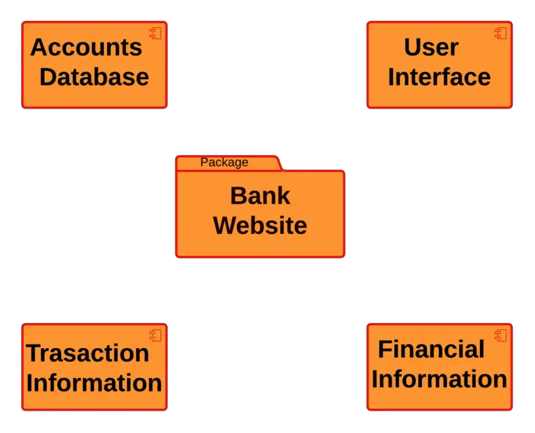
The component symbol is used for a person or thing that needs to do a stereotype function. It gives and takes behavior through interfaces, as well as through other parts. Components can be grouped into a node or another component and can be only one component. - Add the Dependencies (Ports and interfaces)
A dependency is a relationship in which one component needs the information and services of another component, but not always the other way around. To show that one component is relying on another, you should make a connection.
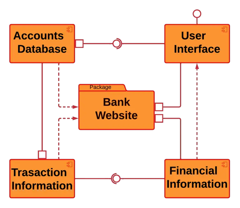
The component’s port is a feature that indicates where the component and its environment meet. In this picture, ports are shown in the form of small squares on the sides of classifiers. It is created when one thing is needed for another thing to work. There is an “include” statement in the makefile for the component that is dependent on the other component.
Interfaces show how components are wired together and how they work together. When a component needs a certain interface, the assembly connector lets you connect it to another component that already has that interface. It looks like a semi-circle and a line.
A component list contains the set of interfaces that a component can use or realize. Components also need interfaces to do their job. It is part of a system that protects the things inside. They are the parts of a system that make sense and play a big part in how a system works.
Conclusion
You need to know the diagrams used to design and develop the Bank Management System. This method is to perfectly create a fully-functional system without unwanted errors and avoid mistakes in development. A component diagram will help you know the components of software and hardware that the project should possess. Not only that, you will find out the needed consideration for the software to work perfectly.
Component diagrams show how a system is put together. During the design phase, software artifacts (classes, interfaces, etc.) of a system are put together into different groups based on how they work together. Now, these groups of things are called parts. Check out our Related and Recommended Articles for more Learning and Information.
Related Articles:
- Component Diagram of Library Management System
- Component Diagram for Hospital Management System
- Component Diagram for Online Shopping System
Recommended Articles from the Author:
- Bank Management System UML Diagrams
- Bank Management System Activity Diagram
- Deployment Diagram for Banking System
- Bank Management System Class Diagram
- Bank Management System Sequence Diagram
Inquiries
If you have inquiries or suggestions about the discussion and illustration for the Component Diagram for Bank Management System, just leave us your comments below. We would be glad to hear to concerns and suggestions and be part of your learning.
Keep us updated and Good day!